Get in Touch with BOSHIYA

Claus Sulfur Recovery: An Engineering Guide to Process, Performance, and RFQ Decisions

Contents
show
Refinery Engineering Guide
Selecting a Claus sulfur recovery unit isn’t as simple as evaluating sulfur capacity. A defensible project starts at the acid-gas feed envelope, defines the scope of recovery, and links the process to tail gas, sulfur handling, utilities, emissions, controls and acceptance tests.
This document provides an enhanced version of the Claus process for the processing and sale of refinery and associated gas. It identifies the decisions that must be made before an SRU can be quoted. It doesn’t provide any global operating setpoints. Hydrogen sulfide and sulfur dioxide are Hazardous, and combustion changes require Qualified Process Safety review.
Some references use the British spelling sulphur. Here sulfur and sulphur describe the same element; spelling doesn’t affect the Claus sulfur recovery process or recovery of sulfur.
Some refineries, natural gas processors, and a few petrochemical plants employ a sulfur recovery system after acid-gas removal. In petroleum refining, that feed gas may come from amine treating and sour water stripping; in natural gas processing, it may come from another desulfurization route.
Start With the System Boundary: SRU Versus the Complete Sulfur-Recovery Train
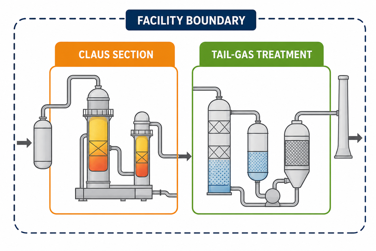
In project terminology, the term SRU may refer to the Claus section only or the entire sulfur recovery section. The broader scope may include acid-gas knock out, a reaction furnace, waste-heat recovery, catalytic reactors, sulfur condensers, tail-gas treatment, incineration, sulfur degassing, liquid-sulfur storage and emission monitoring.
That makes a difference whenever a supplier quotes a recovery percentage. The Claus process converts most incoming hydrogen sulfide into elemental sulfur. A tail-gas treatment unit processes sulfur species that remain downstream. The plant-wide number may also depend on start-up, bypass, and shut-down conditions, sulfur handling losses, and the location where the material balance is closed.
How the Modified Claus Process Converts H2S Into Elemental Sulfur
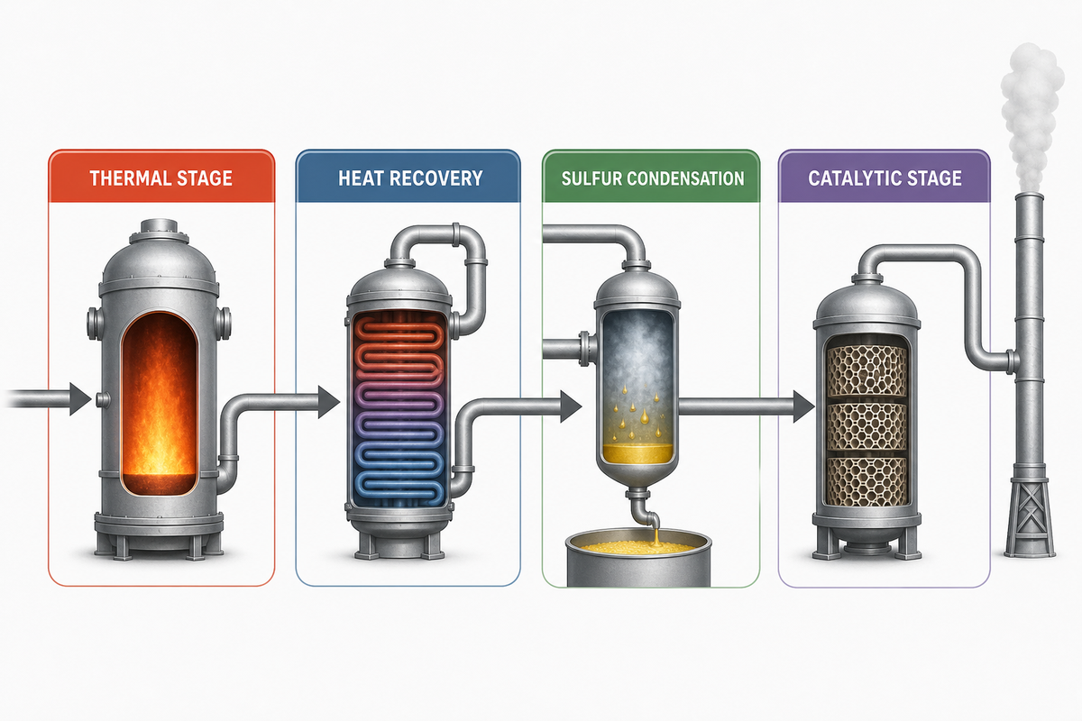
The modified Claus process employs a high-temperature thermal stage and lower temperature catalytic stages. The US EPA sulfur-recovery process description documents this thermal-and-catalytic sequence and its interstage sulfur condensation. In simplified chemistry, part of the hydrogen sulfide is oxidized to sulfur dioxide. The remaining hydrogen sulfide combines with sulfur dioxide to form elemental sulfur and water. Real acid gas contains water and other components, e.g. carbon dioxide and hydrocarbons; hence the overall problem is more complicated than what equation suggests.
The Thermal Stage, Waste-Heat Boiler, and First Condenser
Acid gas and combustion air enter a reaction furnace through a burner. The furnace must provide stable mixing and combustion across the operating envelope while supporting the destruction of problem feed components. The hot gas passes through a waste-heat boiler and then a sulfur condenser, where sulfur vapor condenses into liquid sulfur.
The condenser removes sulfur vapor as a liquid sulfur. Removal of product between reaction stages is part of the conversion strategy; it alters the equilibrium presented to the following stage. The condenser, sulfur seals and drainage, steam supply, and heat tracing serve process functions; therefore, they should be addressed in the process scope and not in the mechanical scope.
Catalytic Conversion, Reheating, and Interstage Condensation
Downstream gas is reheated in a process-gas heat exchanger or another specified reheating system to prevent sulfur from condensing on the Claus catalyst and to put the gas in the right temperature range for the catalytic reaction. After each reactor, another condenser cools the gas to remove more sulfur. A conventional train repeats the sequence of reheat and condense.
Selection and arrangement of catalysts are dependent on the contaminants in the feed, the conversion, the temperature profile, and the process package. Catalyst temperature, air ratio, and furnace air flow for a live unit are unit-specific settings. These must be established by the licensor or a qualified process designer in conjunction with the feed envelope and safety review.
Process-Stage Decision Map
| Stage | Primary job | Buyer question | Evidence to request |
|---|---|---|---|
| Feed handling | Protect the burner from liquid carryover and unstable feed | Which feed cases and contaminants define the design? | Feed envelope, KO basis, alarms, drainage philosophy |
| Reaction furnace | Partial oxidation and required contaminant destruction | How is stable performance demonstrated across turndown? | Heat/material balance, combustion study, burner data |
| Waste-heat boiler | Recover heat and cool process gas | What fouling, corrosion, steam, and inspection cases govern? | Thermal design, metallurgy basis, inspection access |
| Catalytic stages | Continue Claus conversion | Which catalyst duties and replacement assumptions apply? | Bed sizing, catalyst specification, temperature profile |
| Sulfur condensers | Remove sulfur between stages | How are sulfur drainage and low-point risks controlled? | Condenser duty, seals, tracing, drainage details |
| Tail-gas section | Process remaining sulfur species | Is it inside the quoted recovery guarantee? | Boundary diagram, emissions case, guarantee method |
Define the Acid-Gas Feed Basis Before Choosing a Configuration
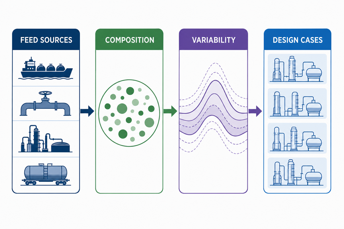
Although two plants may have the same sulfur production rate, they may require different process trains. The US Department of Energy NETL design-parameter guidance illustrates why process models must be tied to an explicit feed and operating basis. One plant may require a conventional process train for H2S-rich sour gases. The other may have a nonconventional process train with a variable AAG stream and an acid gas stream from a sour water stripper containing hydrocarbons and ammonia. Process cases may determine burner type, furnace duty, contaminant destruction requirements, catalyst selection, sulfur condensation requirements, and emissions.
Define design cases for minimum, normal, and maximum operation and for safety review, including start-up, turndown, and upset conditions. Identify if the process streams arrive at the battery limit of the plant separately or are mixed. State the process conditions (temperature, pressure, composition) of the process streams at the battery limit of the plant. Describe the analysis and state the source of the analysis.
Acid-Gas Feed-Basis Checklist
- State the expected duration, frequency and cases for which process flow and mass and molar balances are required.
- H2S, CO2, water, hydrocarbons, ammonia, hydrogen, and other relevant compounds.
- State minimum, normal and maximum conditions at the battery limit.
- Source unit, expected variability, sampling method, and laboratory uncertainty.
- Liquid carryover risk, upstream knock-out performance, drains and alarm interfaces.
- Required sulfur capacity, turndown, train availability, start-up philosophy, and anticipated cases.
- Site ambient conditions, fuel gas, instrument air, steam, cooling medium, and power.
Only when bounded cases are provided to all bidders can a responsible vendor make an equivalent proposal. When cases are uncertain, the best approach is to request suppliers to provide a guaranteed performance case and sensitivity case. This is preferable to allowing individual bidders to select an average case.
Why Quoted Recovery Depends on Where the Boundary Is Drawn
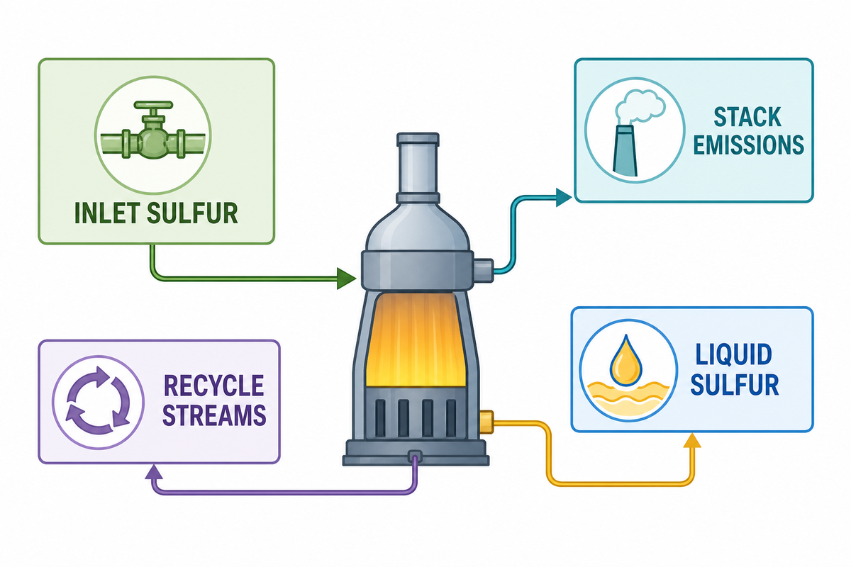
In the EPA process description, conventional Claus recovery is thermodynamically limited, while reported practical recovery depends on the number of catalytic stages and operating conditions. The boundary distinction is reflected in the US EPA AP-42 sulfur-recovery chapter, which describes Claus conversion and downstream tail-gas control separately. Tail-gas treatment increases overall sulfur recovery beyond that achieved in the Claus section. The exact value is configuration and condition dependent. It shouldn’t be put in a purchase specification to serve as a general assurance.
| Claim | Possible boundary | What the buyer must clarify |
|---|---|---|
| Claus recovery | Reaction furnace through final Claus condenser | Feed case, number of stages, equilibrium/model basis, sulfur species counted |
| Overall sulfur recovery | Claus section plus tail-gas treatment | TGTU technology, recycle location, absorber performance, emissions boundary |
| Annual recovery | Operating year including downtime or bypass | Availability assumptions, start-up/shutdown treatment, excluded periods |
| Emission guarantee | Incinerator stack or another permit point | Pollutant, averaging period, oxygen correction, test method, operating case |
Request bidders to disclose the material-balance points for inlet sulfur, sulfur produced as the liquid by-product, recycle streams, gas volume, and stack emissions. Without those points, a quoted recovery percentage can’t be tested at handover or compared across bids.
Configuration Decisions That Change the Project
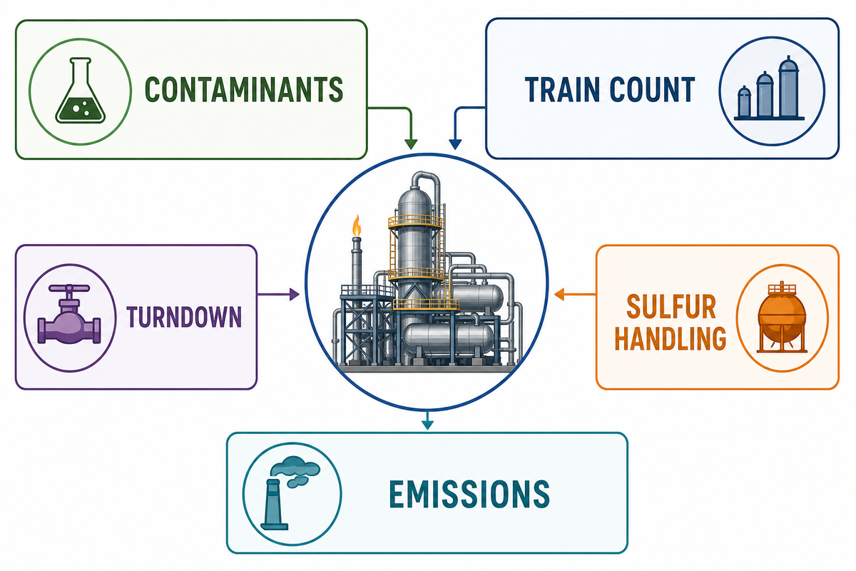
Feed Contaminants and Destruction Requirements
Ammonia, hydrocarbons, water, and other contaminants can affect combustion, deposits, corrosion, catalyst condition, and emissions. The project must define what must be destroyed, what can be separated upstream, and permitted feed combinations. Supporting evidence must include design cases and analytical methods. A general statement that the unit “handles contaminants” isn’t sufficient.
Turndown, Train Count, Redundancy, and Maintenance
One large train may reduce duplicated equipment, but two trains may better align availability and staged capacity and maintenance objectives. The right choice depends on constraints and permissive routing during outages of upstream units, minimum stable load, spare philosophy, and effects of losing sulfur recovery capacity.
Define what critical pumps, analyzers, blowers and controls require installed spares. State what maintenance activities must be possible online. Behind a “2 × 50%” label, ask which systems and constraints the trains share and whether one train can accept upset flow.
Sulfur Handling, Degassing, Incineration, and Emissions Interfaces
Liquid sulfur leaving the condensers still requires safe collection, degassing (if needed), storage, heating, transfer, loading and vapor management. Tail gas requires a defined destination during normal operation and approved transient states. The incinerator, stack, analyzers, sampling points and permit boundary must be included in the Interface Schedule.
Oxygen enrichment can sometimes be used as a debottlenecking or capacity option in some processes, but this will change the thermal and equipment reviews. Linde’s Claus-plant oxygen-enrichment overview provides a supplier reference for evaluating that option as an engineered process change. This should be treated as a more detailed engineered case and considered in combination with burner, furnace, waste-heat boiler, control, oxygen supply, materials, and safety reviews, and not as a general capacity switch.
The Claus reaction creates project-specific side-chemistry questions. A qualified design review considers the SO2 balance, possible COS and CS2 conversion, sulfur content in the remaining gas, and the first catalytic reactor temperature profile. The second condenser and later stages should be examined as an integrated system.
Interfaces with adjacent equipment affect layout and maintenance. For related refinery equipment context, see Boshiya’s API 660 heat-exchanger standards guide and hydrocracking versus hydrotreating guide. A process-gas exchanger, sulfur pipe, effluent connection, and thermal oxidizer interface can constrain layout and maintenance. Crude oil distillation doesn’t belong inside the SRU boundary, but the wider crude refining scheme will determine which acid-gas sources reach it.
Gasification projects may use Rectisol or Selexol upstream, while a refinery sour-gas system is downstream of amine treating. Boshiya’s guides to industrial ammonia production and catalytic reforming provide adjacent process context without changing this guide’s sulfur-recovery intent. These aren’t interchangeable design labels; each upstream route impacts the feed basis provided to the Claus unit.
Performance Limits and an Upset-Diagnosis Map
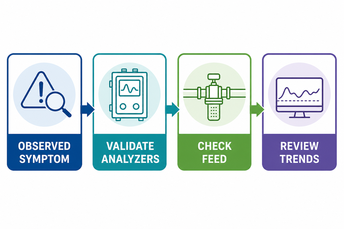
Claus performance depends on conditions throughout the process train. The presence of higher sulfur species in tail gas may be indicative of air-demand control, feed composition, reaction temperature, catalyst condition, bypass leakage, sulfur condensation, hydraulic loading, or analyzer problems. The symptom alone doesn’t provide the root cause. The Digital Refining discussion of ammonia destruction is one example of why furnace conditions, feed contaminants, and downstream symptoms must be evaluated together.
| Observed symptom | Investigation categories | Evidence to review first |
|---|---|---|
| Higher tail-gas sulfur | Feed change, air-demand control, catalyst activity, bypass leakage | Validated analyzers, feed assay, trend data, valve status |
| Unstable furnace operation | Feed mixing, liquid carryover, burner range, fuel support, draft | Trip history, KO performance, burner study, pressure trends |
| Rising reactor pressure drop | Deposits, catalyst damage, sulfur condensation, refractory debris | Temperature profile, differential pressure, shutdown inspection |
| Poor sulfur drainage | Tracing, seals, low points, condenser duty, plugging | Steam/heat tracing records, level trends, line inspection |
| Emission excursions | SRU conversion, TGTU performance, incineration, analyzer validity | Mass balance, operating mode, CEMS checks, permit method |
This map is to provide information for initial assessment and to define scope. Operations should follow approved operating procedures to make any changes to combustion, bypass or protection settings.
The Claus SRU RFQ Checklist Buyers Can Reuse
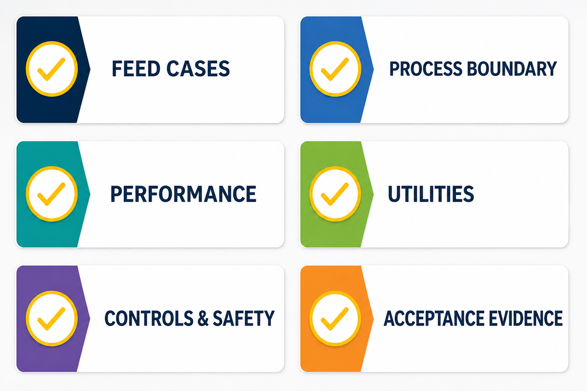
You want bidders to price the same boundary conditions and identify exceptions. The NETL design-parameter framework reinforces the procurement value of stating common modeling inputs, cases, and boundaries before comparing proposals. Include a battery-limit diagram, and require a completed Compliance Table for every proposal.
- Feed cases: compositions, flow, pressure, temperature, variability, contaminants, and sampling basis.
- Performance: sulfur capacity, turndown, recovery and emission limits, availability case, and guarantee test.
- Process scope: thermal and catalytic stages, reheating method, tail-gas treatment, incineration and sulfur degassing.
- Mechanical scope: metallurgy, refractory, corrosion allowance, design codes, inspection access, and preservation.
- Utilities: steam levels, cooling medium, fuel gas, power, nitrogen, instrument air, drains, flares.
- Control and Safety: air-demand control, analyzers, SIS/ESD boundaries, Cause-and-Effect relationships, alarms and trips, and hazardous areas.
- Layout: maintenance clearances, lifting and modularization, transport envelope, tie-in schedule.
- Documentation: heat and material balances, PFDs and P&IDs, datasheets, calculations, manuals, certificates, and vendor data.
- Testing: shop inspections, FAT, refractory dry-out, catalyst loading, commissioning, performance test, and punch list.
- Exceptions: explicit exclusions, assumptions, owner-supplied, licensor interfaces, and optional prices.
| RFQ category | Minimum returnable | Why it prevents bid ambiguity |
|---|---|---|
| 1. Feed basis | Case-by-case heat and material balance | Exposes composition and flow assumptions |
| 2. Process configuration | PFD with stage and recycle boundaries | Shows what the sulfur recovery process includes |
| 3. Performance | Recovery, capacity, emissions, and turndown guarantees | Makes the guarantee boundary testable |
| 4. Equipment | Major datasheets and design conditions | Reveals the proposed sulfur recovery unit scope |
| 5. Materials | Metallurgy and refractory selection basis | Connects materials to temperature and corrosion cases |
| 6. Utilities | Consumption table by operating case | Prevents hidden owner loads |
| 7. Controls | Control narrative and analyzer list | Defines air demand and protective functions |
| 8. Layout | Plot plan and maintenance envelopes | Tests site and modularization fit |
| 9. Documentation | Vendor-data and review schedule | Clarifies engineering deliverables |
| 10. Acceptance | Inspection, FAT, commissioning, and performance-test plan | Connects purchase terms to evidence |
Acceptance Evidence: What to Verify Before Handover
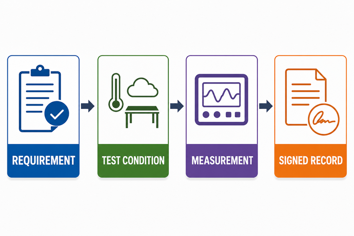
Prior to purchase, an acceptance test plan should be provided. Mechanical completion, by itself, doesn’t confirm conversion, emissions, turndown, or control requirements. Define representative feed cases and state how the results of the test case will be normalized to the case for which the guarantee has been provided.
Request calibrated instrument records, feed and product sampling methods, sulfur mass-balance logic, stack test procedures, analyzer validation, utility measurements, and a list of permitted exclusions. Indicate whether you consider startup, bypass, and off-spec periods to be included. Require resolution rules for a test that can’t reach the guaranteed feed condition.
Don’t consider the purchase-order boundary to be the regulatory facility boundary. For example, U.S. refinery requirements can specify which sulfur recovery equipment and sulfur pits belong to a regulated facility, address how or which emission results are corrected or combined, and stipulate continuous emission monitoring for a specified averaging period. In the U.S. refinery standard, for example, an air-fired Claus unit in a large plant with oxidation control, or reduction control followed by incineration, has an SO2 emissions limit of 250 ppmv (dry basis) at zero percent excess air; other jurisdictions set their own limits. However, they demonstrate that one acceptance test or one overall sulfur recovery percentage can’t, by itself, demonstrate that continued compliance with emissions regulations has been achieved.
Keep the following three evidence packages separate: the contractual equipment guarantee, the permit or regulatory emission demonstration, and the continuing monitoring and quality-assurance record. For a US regulatory example, 40 CFR 60.106a sets monitoring provisions that are distinct from a vendor’s contractual performance test. The owner should identify the applicable environmental regulations, emission points, pollutant basis, averaging time, correction method, and data-validity criteria with qualified environmental counsel or engineers.
Proposal Comparison Scorecard
| Decision | Bidder A | Bidder B | Owner check |
|---|---|---|---|
| Feed cases accepted without exception | Record | Record | Same basis? |
| Recovery and emission boundary | Record | Record | Same measurement points? |
| Turndown and train availability | Record | Record | Same operating modes? |
| Utilities and owner scope | Record | Record | Lifecycle impact? |
| Guarantee and acceptance method | Record | Record | Testable on site? |
Decision Framework: From Feed Assay to Vendor Inquiry
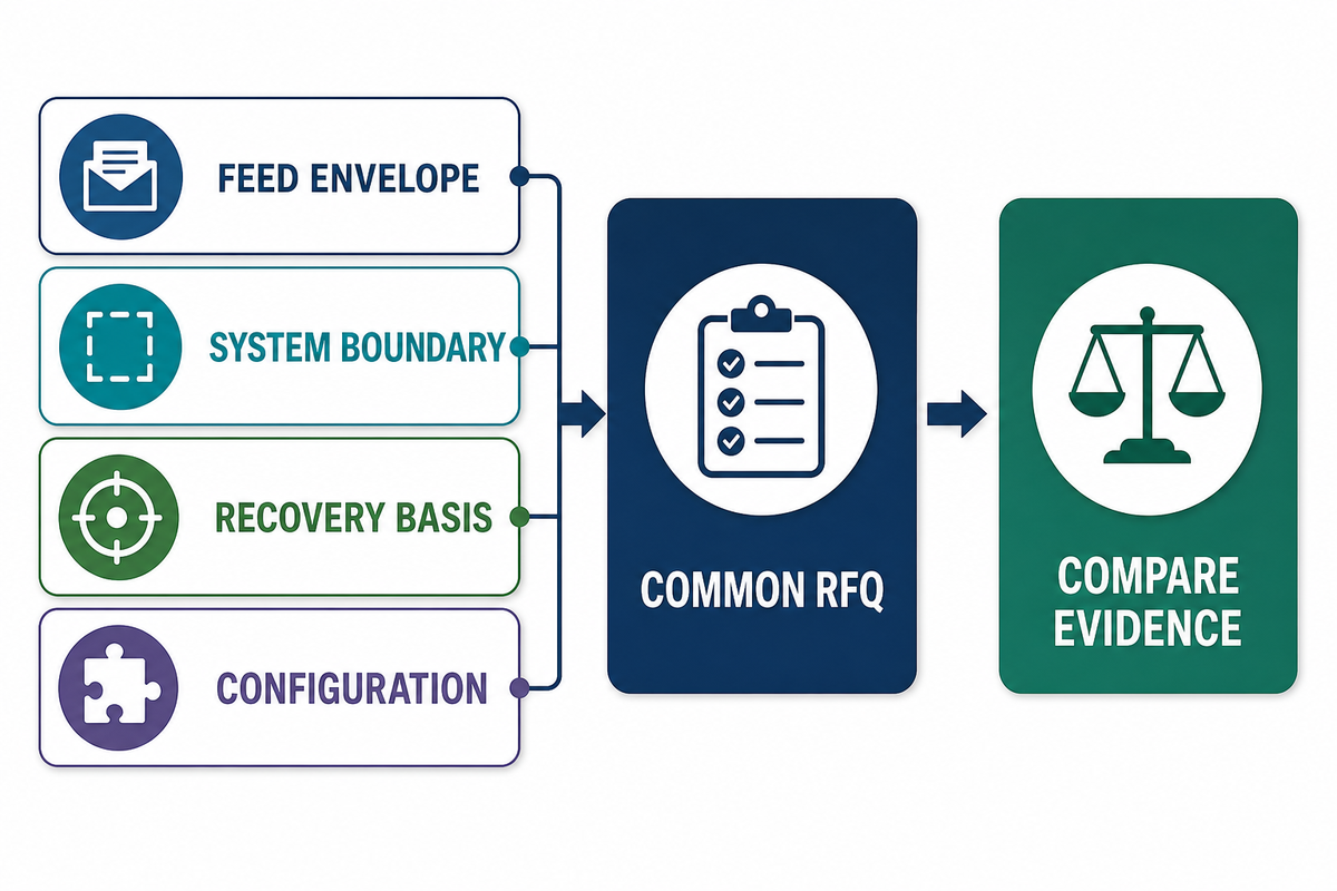
First, define a bounded acid-gas feed envelope and then delineate the entire sulfur recovery train and battery limits. Use the US EPA refinery background document as an external reference for keeping process equipment, emission points, and facility boundaries explicit during that sequence. Next, determine the recovery and emission measurement boundary. Then, define the process train redundancy and turndown, sulfur handling, and tail-gas philosophy. Next, issue the same compliance table and RFQ to all bidders. Lastly, evaluate and accept technical exceptions and then compare price.
Boshiya can use this defined basis to discuss the refinery equipment scope and fabrication interfaces. When proprietary Claus or tail-gas technology is involved, keep the licensor, process designer, equipment fabricator, and site owner responsibilities distinct.
Frequently Asked Questions
What is Claus sulfur recovery?
Claus sulfur recovery is an industrial process that converts hydrogen sulfide in acid gas into elemental sulfur. The modified process employs a thermal stage, sulfur condensation, and one or more catalytic conversion stages.
What is the difference between an SRU and a TGTU?
The SRU generally refers to the Claus conversion section. A TGTU can increase overall sulfur recovery and can be placed outside the quoted boundary. Project documents must define the location of the TGTU.
How efficient is the Claus process?
The EPA reports roughly 92% to 97% recovery across conventional two- to four-stage Claus configurations, while final performance is determined by feed, stages, controls, and other operating conditions. With tail-gas treatment, overall recovery can rise further: one published technology review groups those processes into ones that attain 99% and ones that achieve 99.9%, including the sulfur recovered in the Claus unit. Make sure guarantees are compared on the same basis; determine which sulfur species are included; ascertain test feed and the averaging period; distinguish design-case conversion from annual recovery which can include start-up, shut-down, bypass and downtime.
What data is needed to size a sulfur recovery unit?
Provide information on bounded acid gas flow, composition, pressure, temperature, contaminants, variability, turndown, sulfur capacity, utilities, emissions requirements, availability philosophy, battery limits, and other future cases. Average H2S concentration by itself isn’t a sufficient basis for design.
Can one Claus configuration handle every acid gas?
No. H2S strength, ammonia, hydrocarbons, water, carbon dioxide, pressure, variability, and required destruction performance affect configuration. The selected route must be engineered against the feed component envelope and applicable safety and environmental requirements.
References & Sources
- US EPA, AP-42 Section 8.13: Sulfur Recovery
- Penn State, Claus Process overview
- US EPA, Petroleum Refineries background information
- 40 CFR 60.101a, definitions for applicable US refinery facilities
- 40 CFR 60.102a, applicable emissions requirements
- 40 CFR 60.106a, monitoring requirements
- US DOE NETL, process modeling design parameters
- Linde, oxygen enrichment for Claus plants