Get in Touch with BOSHIYA


Catalytic reforming is a refinery process that upgrades low octane naphtha into high-octane gasoline blending components, aromatics, and hydrogen. It’s a refinery value unit, not a stand-alone chemistry trick. In the plant, the unit sits between naphtha pretreating, reactor heating, product separation, recycle gas, reformate stabilization, and downstream gasoline or petrochemical routing.
Contents
show
BLUF for refinery teams
Treat the reformer as an octane, aromatics, hydrogen, and reliability system. A better catalyst plan won’t rescue poor feed pretreatment, weak heat recovery, restricted bundle access, or a turnaround plan that misses the feed-effluent exchanger and recycle-gas train.
| Quick spec | Practical meaning |
|---|---|
| Main feed | Straight-run heavy naphtha or treated naphtha feedstock from crude oil distillation and hydrotreating. |
| Main products | Reformate for the gasoline pool, hydrogen gas for refinery hydrotreating, and aromatic compound streams such as benzene, toluene, and xylene. |
| Common catalyst base | Platinum on alumina, often modified in licensed systems; sulfur, nitrogen, water, and metals shorten active life. |
| Equipment watch point | Feed-effluent heat exchange, fired-heater duty, reactor pressure drop, separator performance, recycle gas compression, and turnaround access. |
What Is Catalytic Reforming?
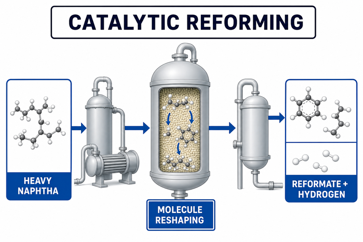
Catalytic reforming is a petroleum refining process that rearranges hydrocarbons with low octane numbers into higher octane reformate. In plain terms, a refinery takes heavy naphtha, removes feed poisons, heats it through a catalytic reformer, and recovers a liquid blending stock plus hydrogen byproduct. The U.S. Energy Information Administration explains the route as a way to raise gasoline octane and produce useful aromatic streams.
Start with the word “reforming.” Naphtha isn’t simply cracked into smaller pieces. Inside the reactor, hydrocarbon molecules are reshaped through dehydrogenation, isomerization, dehydrocyclization, and limited hydrocracking. Penn State’s refinery course frames the output as low-sulfur, high-octane reformate with hydrogen as a valuable co-product.
That makes the unit sensitive to both chemistry and hardware. Feed quality controls much of the catalyst activity. Product value depends on octane rating, benzene content, total aromatics, and gasoline blending limits. Plant uptime depends on heater, reactor, exchanger, separator, compressor, and stabilizer conditions that maintenance teams can actually inspect.
Where Catalytic Reforming Fits in an Oil Refinery
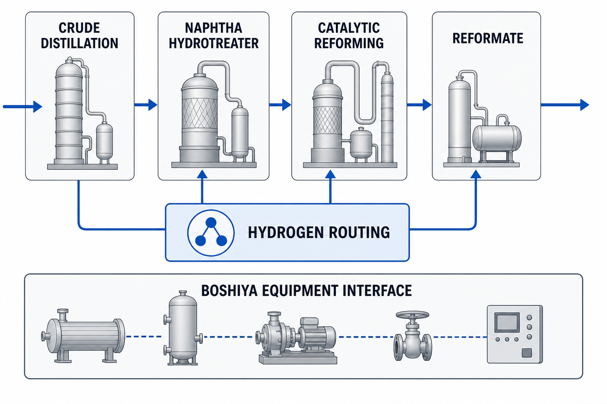
In a crude oil refinery, heavy naphtha is the reformer feed context after the crude distillation unit splits the barrel by boiling range. Light naphtha may move toward an isomerization unit. Heavy naphtha normally becomes reformer feed after a naphtha hydrotreater removes sulfur and nitrogen compounds that would poison the reforming catalyst.
After pretreating, feed moves through heat recovery, fired heating, a series of reactor beds, effluent cooling, high-pressure separation, recycle gas handling, and stabilization. Liquid product leaves as reformate, a high-octane gasoline blending component. Hydrogen is routed to refinery consumers such as hydrotreaters. BTX-rich streams may support petrochemical routes when the refinery has extraction capacity.
For equipment planning, the right handoff isn’t a claim that one supplier owns the whole licensed technology. It is a practical interface map. BOSHIYA’s oil refinery equipment and petroleum refining solutions page is the internal next step for teams reviewing heat exchanger maintenance, bundle extraction, pressure vessels, refinery turnaround work, and related plant hardware around oil refinery units.
The 9-Step Naphtha-to-Reformate Value Chain
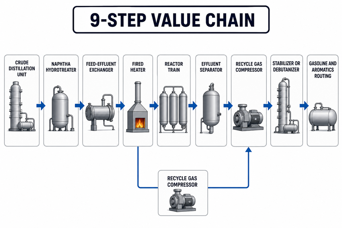
9-Step Naphtha-to-Reformate Value Chain turns a chemistry topic into a refinery decision map. Penn State’s catalytic reformer material is the authority anchor for reading feed pretreatment, catalyst, reformate, and hydrogen as one connected refinery system. Each step creates a different failure mode, so teams should review evidence by interface rather than by one average reformer yield.
| Process step | Plant area | Value created | Watch point |
|---|---|---|---|
| 1 | Crude distillation unit | Straight-run naphtha fraction | Cut point and feed variability |
| 2 | Naphtha hydrotreater | Sulfur and nitrogen removal | Guarding platinum catalyst life |
| 3 | Feed-effluent exchanger | Heat recovery before furnace firing | Approach temperature and fouling |
| 4 | Fired heater | Reaction temperature lift | Tube skin and fuel duty |
| 5 | Reactor train | Octane number gain and aromatics formation | Pressure drop and coke |
| 6 | Effluent cooling and separator | Liquid and hydrogen-rich gas split | Carryover and gas purity |
| 7 | Recycle gas compressor | Hydrogen partial pressure control | Reliability and seal plan |
| 8 | Stabilizer or debutanizer | Stable reformate and light ends | Reboiler and condenser duty |
| 9 | Gasoline and aromatics routing | High octane, BTX, hydrogen balance | Benzene content and product slate |
Key Reactions: Dehydrogenation, Isomerization, Dehydrocyclization, and Hydrocracking
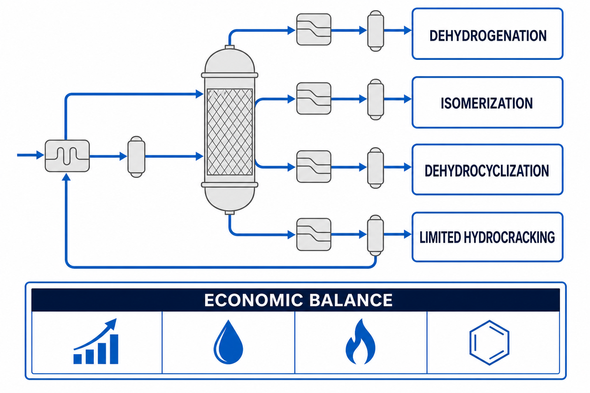
The main reactions in catalytic reforming are easier to read as refinery outcomes. Dehydrogenation turns naphthenes into aromatic molecules and releases hydrogen. Isomerization rearranges paraffin structures so the octane rating rises. Dehydrocyclization converts some paraffins into ring structures. Limited hydrocracking produces lighter hydrocarbons, including butane and other light ends, but too much cracking reduces liquid reformate yield.
Reformer economics therefore balance octane, liquid yield, hydrogen, and aromatic content. Patent background on staged catalytic reforming commonly places conventional reforming reaction conditions in the range of about 450°C to 560°C and 1 bar to 50 bar, but those numbers aren’t a startup recipe. Actual reaction temperature, pressure, recycle ratio, feed quality, and licensed reactor design belong to site-specific process engineering.
For a buyer or maintenance planner, the practical boundary is simple: don’t specify only “high octane gasoline.” Ask which molecule route creates the value, which constraint limits the unit, and which equipment item is most likely to make that constraint worse during the next 12 months of operation.
Catalytic Reforming Catalysts and Regeneration
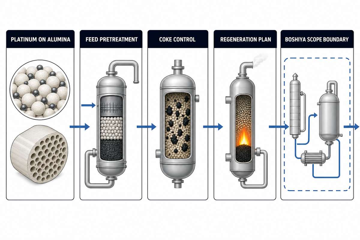
Industrial reforming catalysts contain platinum in many standard explanations, often on an alumina support. Springer’s petroleum-processing reference treats catalyst deactivation, regeneration, reactions, process conditions, and economics as linked topics. Modern licensed systems may use bimetallic chemistry, but the buyer-side lesson isn’t a brand list. Protection is the lesson. Sulfur, nitrogen, oxygen compounds, water, chloride loss, metals, and coke change the activity of the catalyst and shorten the useful run.
Feed pretreatment is the first defense. A naphtha hydrotreater protects the reactor train before the reforming process begins. Coke is the second defense problem. As severity rises, carbon deposits can build on active sites. Each plant then needs a regeneration plan matched to unit design, whether the site uses continuous catalyst regeneration, cyclic regeneration, or a semi-regenerative shutdown interval.
“The expensive question is rarely whether the catalyst works in isolation. It is whether the feed, heater, recycle gas, exchanger, and turnaround window let it keep working.”
This article doesn’t claim BOSHIYA supplies reforming catalyst or licenses the process. Verified brand evidence connects BOSHIYA with oil refinery equipment, heat exchanger maintenance, bundle extraction, pressure vessels, and turnaround hardware that can influence uptime around reforming units.
Catalytic Reforming Process Flow: Pretreating, Furnaces, Reactors, Separators, and Recycle Gas
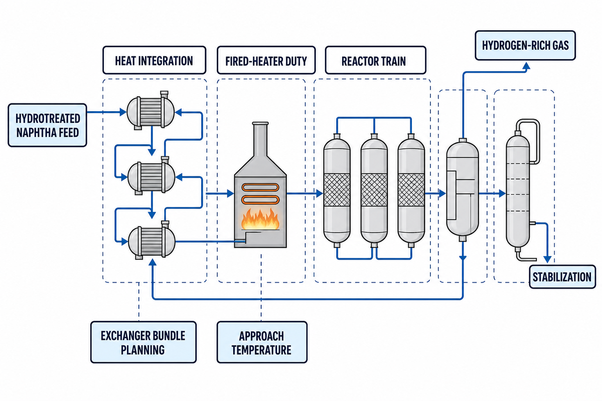
A catalytic reforming unit normally starts with hydrotreated naphtha feed, then uses heat integration and furnace firing to reach reaction temperature. Penn State’s process overview supports the same feed, catalyst, reformate, and hydrogen sequence. Many reactor sections include 3 or 4 reactors with interheaters because reforming reactions are strongly endothermic. After the reactor train, effluent cooling and separation recover hydrogen-rich gas for recycle and a liquid stream for stabilization.
Refinery Interface Checklist
- Confirm feed pretreatment targets before blaming a reforming catalyst.
- Trend feed-effluent exchanger pressure drop and approach temperature.
- Review fired-heater duty, tube skin limits, and air/fuel controls.
- Track reactor inlet temperature spread across each bed.
- Check separator temperature, pressure, and liquid carryover.
- Review recycle gas compressor reliability and hydrogen purity.
- Plan exchanger bundle pulling, cleaning, inspection, and gasket logistics before turnaround freeze.
Supplier application references describe hydrotreated naphtha, hydrogen recycle, separator gas reuse, stabilizer or debutanizer bottoms as reformate, and aromatics extraction routes. Heat-transfer references place special weight on the feed-effluent exchanger; one published application page reports close to a 10 deg C hot-end approach, more than 50% fired-heater energy reduction, capacity increase claims up to 33%, and roughly 300 delivered Packinox references. Treat those as vendor-specific application claims, not universal guarantees.
| Review signal | Published value to capture | Why it belongs in the file |
|---|---|---|
| Hot-end approach | 10°C application reference | Shows whether heat recovery is drifting before heater duty rises. |
| Vendor heat-duty claim | 50% fired-heater energy reduction claim | Sets a published benchmark, not a guarantee for every unit. |
| Capacity claim | 33% increase claim | Flags why exchanger replacement can enter revamp economics. |
| Application reference base | 300 delivered references | Separates a single brochure claim from a larger installed base claim. |
| Temperature background | 450°C to 560°C patent-context range | Keeps the article grounded while avoiding operating instructions. |
| Pressure background | 1 bar to 50 bar patent-context range | Shows why reactor pressure is a design variable, not a blog prescription. |
| Outage sensitivity | 1 day restart delay | Makes bundle access and cleaning sequence visible to procurement. |
| Cleaning window | 2 days to 3 days planned work | Gives maintenance teams a place to test crane path and cleaning capacity. |
| Trend window | 90 days, 12 months, and 24 months | Separates short upset noise from fouling and catalyst-cycle drift. |
Operating Variables That Change Octane, Yield, and Run Length
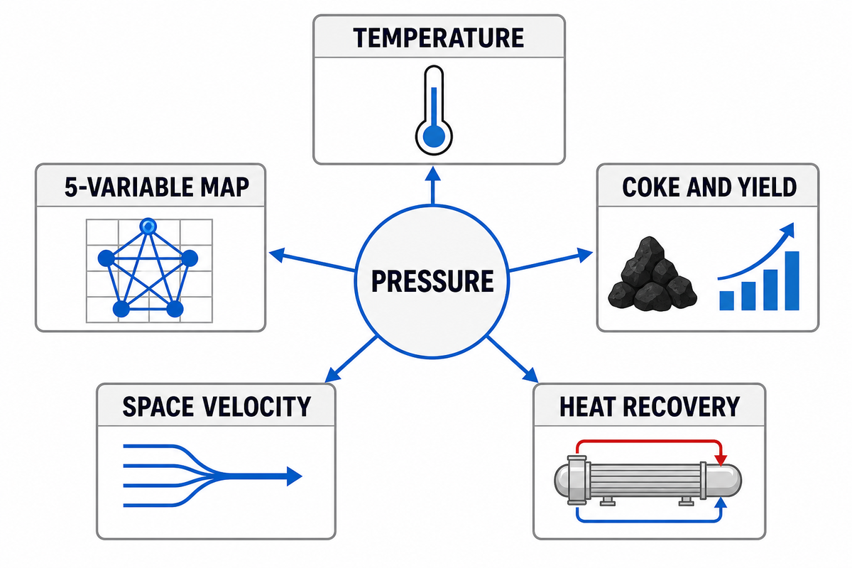
The 5-Variable Octane-Hydrogen Tradeoff Map is a way to avoid the common mistake of asking for higher severity without checking what it costs. EIA’s octane-focused refinery explainer supports the value side of the tradeoff, while unit teams still need to test its operating cost. Higher temperature may lift octane, but it can also increase coke, reduce liquid yield, raise fuel use, and shorten the run length between regeneration events.
| Variable | If pushed higher | Possible penalty | What to trend |
|---|---|---|---|
| Reactor temperature | Higher octane and more aromatics | More coke and heater duty | Inlet spread, fuel rate, skin temperature |
| Pressure | More hydrogen partial pressure | Lower aromatics equilibrium in some modes | Recycle gas, compressor load, separator pressure |
| Space velocity | More throughput | Less residence time and lower conversion | Feed rate, octane number, endpoint |
| Feed quality | More naphthenes improve reformability | More paraffin-heavy feed may need severity | PONA data, sulfur, nitrogen, chloride balance |
| Heat recovery | Lower fired-heater load | Fouling can hide behind normal feed rate | Approach temperature, pressure drop, cleaning history |
Hydrogen pressure is part of the same tradeoff. Penn State’s catalytic conversion lesson notes that low hydrogen pressure can promote desired reforming equilibrium, while enough hydrogen pressure is still needed to inhibit coke on catalyst surfaces. That is why “more severe” is not a single-direction command.
Counterintuitively, the highest severity target may not be the most profitable target. A refinery might prefer a lower octane target if it protects liquid yield, hydrogen balance, catalyst cycle length, or product benzene content. That target changes with crude slate, gasoline pool demand, aromatics extraction value, and maintenance timing.
Continuous Catalytic Reforming vs Semi-Regenerative Reforming
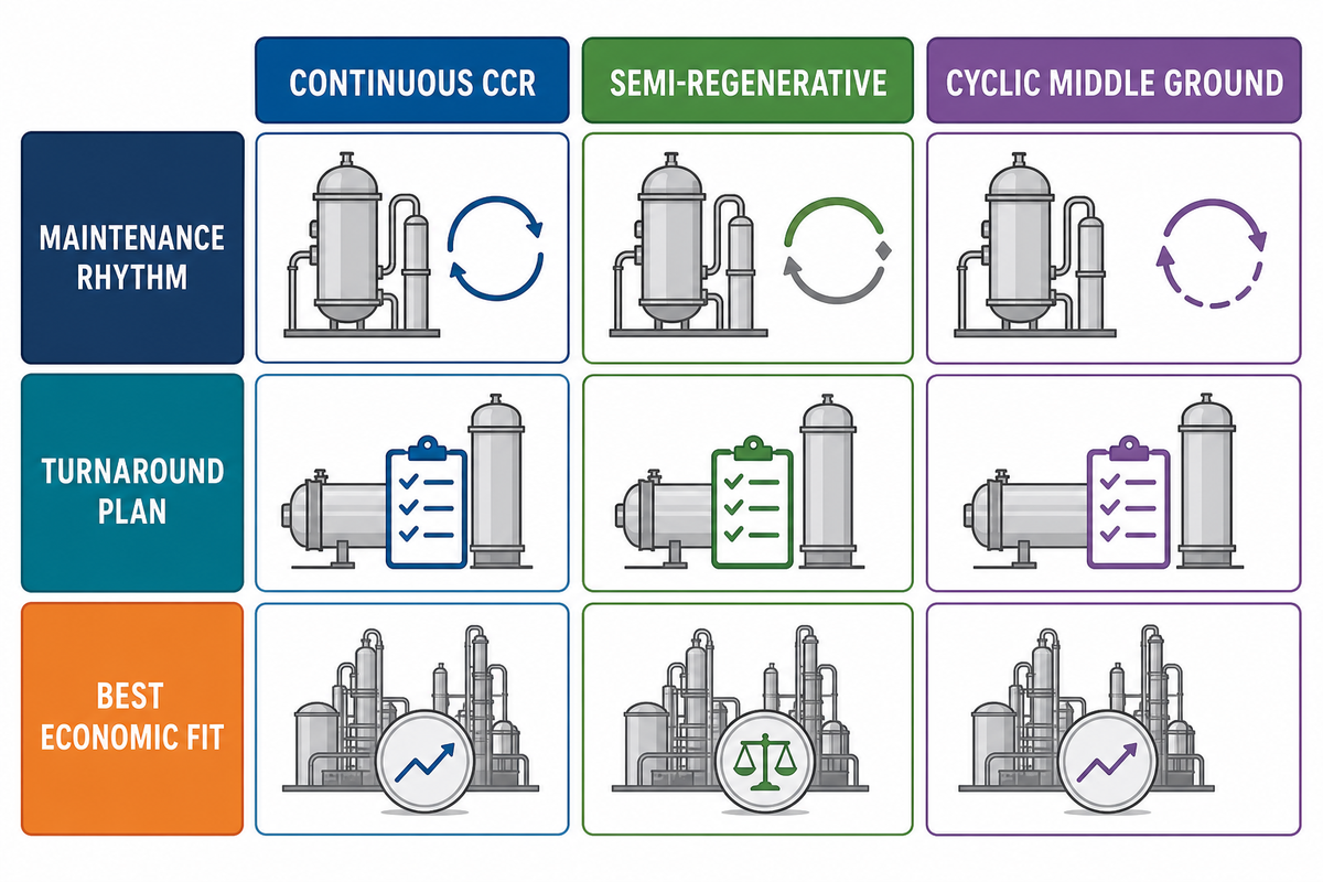
Continuous catalytic reforming, often shortened to CCR, moves catalyst through a regeneration circuit while the catalytic reformer unit remains on stream. Patent literature on staged reforming and catalyst circulation is useful background for this mode boundary. Semi-regenerative catalytic reformers hold fixed beds in service until activity drops enough to justify a shutdown and regeneration. A third configuration, cyclic reforming with a swing reactor, is also recognized in refinery references, so the practical choice is not always a clean two-box comparison.
| Decision point | CCR route | Semi-regenerative route |
|---|---|---|
| Run length | Designed for longer on-stream severity through continuous catalyst regeneration. | Run length is tied to fixed-bed deactivation and planned outage windows. |
| Cyclic middle ground | Not the usual CCR case; review any swing-reactor arrangement separately. | Not the usual full shutdown case; one reactor may be isolated while others keep running. |
| Complexity | Adds moving catalyst handling, regeneration vessels, lift gas, and extra controls. | Simpler reactor train but less freedom to push severity late in cycle. |
| Maintenance rhythm | More online systems to monitor, fewer full-unit regeneration shutdowns. | Turnaround plan must include catalyst work, heater, exchanger, and vessel access. |
| Best economic fit | High severity, high octane, strong hydrogen or aromatics value, large throughput. | Moderate severity, lower complexity, or revamp settings where capital discipline dominates. |
Penn State lists semi-regenerative, cyclic, and continuous catalytic reforming, while OSHA also notes units that regenerate continuously, one reactor at a time, or all reactors during turnarounds. Treat the table as a procurement starting point, then confirm the actual licensed configuration and regeneration hardware on the site P&ID.
Use the 4-Route CCR-vs-Semi-Regenerative Decision Grid to start with product value and outage cost, then move to unit hardware. If exchanger cleaning needs 2 days, catalyst handling needs 3 days, and compressor inspection needs 1 day, the theoretical mode advantage is only useful when the turnaround sequence can support it.
Catalytic Reforming vs Catalytic Cracking vs Steam Reforming
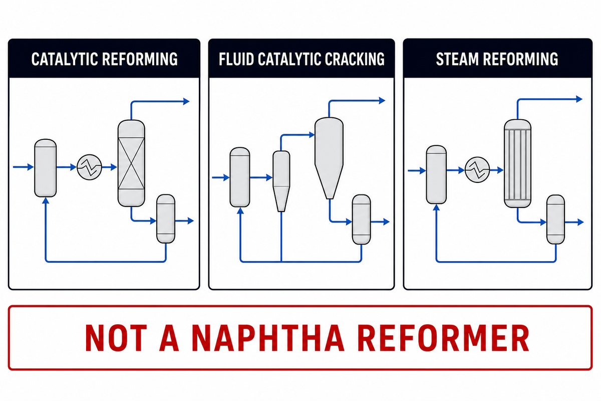
The three terms sound similar, but they solve different refinery problems. Catalytic reforming of petroleum rearranges naphtha molecules to raise octane and produce reformate. Fluid catalytic cracking breaks heavier gas oils into lighter gasoline-range molecules and olefins. Steam reforming reacts light hydrocarbons with steam to make synthesis gas and hydrogen; it isn’t the same as a naphtha reformer for gasoline blending.
| Process | Feedstock | Primary target | Do not confuse it with |
|---|---|---|---|
| Catalytic reforming | Heavy naphtha, straight run naphtha | Reformate, octane, aromatics, hydrogen byproduct | Catalytic refining as a broad phrase |
| Fluid catalytic cracking | Vacuum gas oil or heavier fractions | Gasoline-range molecules, LPG, propylene | A catalytic reformer |
| Steam reforming | Methane, natural gas, or light hydrocarbons | Hydrogen and syngas | Naphtha reformate production |
This boundary is useful for content planning too. A refinery site may already have a fluid catalytic cracker guide, an alkylation unit page, or a general petroleum refining solutions page. Here, the reforming article should answer the octane, aromatic, hydrogen, and reformer maintenance questions that those pages don’t answer.
Maintenance Interfaces: Heat Recovery, Turnaround Access, and Reliability
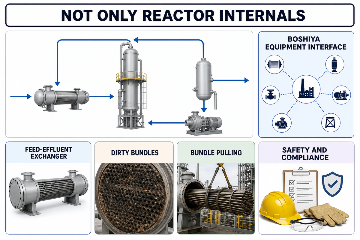
Reformer maintenance isn’t limited to the reactor internals. Because the refinery-course source connects catalyst protection with feed pretreatment and reformer operation, hardware reliability has to be reviewed beside the chemistry. A feed-effluent exchanger may decide how much fired-heater duty is needed. Dirty bundles can raise fuel use before the unit misses product specs. Difficult bundle pulling can stretch the outage even when the catalyst work is ready. Recycle compressor faults can move hydrogen balance and limit severity.
BOSHIYA’s role should be framed at that equipment interface. Public BOSHIYA pages describe oil refinery equipment, shell-and-tube heat exchangers, reactors, pressure vessels, bundle extraction, cleaning equipment, ASME/API/ISO references, 109 years of operation, 43 countries served, and 60K MT/year manufacturing capacity. Those facts support a refinery-equipment discussion; they do not prove process licensing or proprietary reforming chemistry.
The maintenance file also needs safety and compliance boundaries. OSHA’s petroleum-refining process guidance calls out reformer startup hot spots, catalyst fines plugging screens, ammonium-chloride corrosion or fouling, reformate or hydrogen fire risk, and potential benzene or hydrogen-sulfide exposure during leaks, regeneration, inspection, maintenance, and turnaround work. U.S. gasoline benzene standards and 40 CFR Part 98 Subpart Y refinery reporting rules also keep reformer regeneration, coke burn-off emissions, and benzene control in the review envelope.
Turnaround review prompt
Before freezing a reformer outage plan, list every exchanger bundle, pressure vessel, access constraint, crane path, cleaning station, gasket set, and inspection hold point that can delay restart by 1 day. Then test the plan against the real equipment layout, not only the process flow diagram.
How to Use This Guide in a Reformer Review
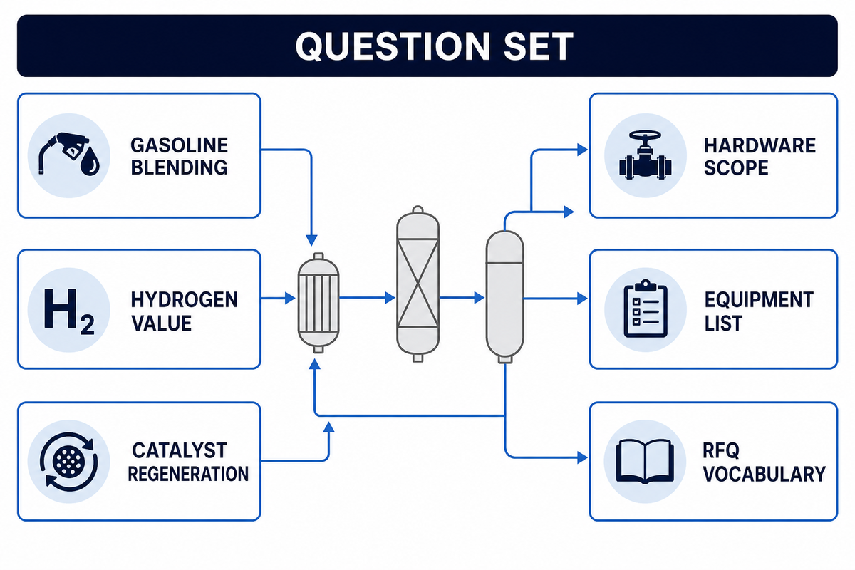
Use this guide as a question set. If the discussion is about gasoline blending, ask how much reformate octane is needed and how benzene content will be managed, using EIA’s reformate and aromatics framing as the public baseline. If the discussion is about hydrogen, ask whether the refinery values byproduct hydrogen more than marginal liquid yield. If the discussion is about catalyst regeneration, ask whether feed pretreatment, recycle gas, and heater limits support the desired cycle.
If the discussion is about hardware, move from the PFD to the equipment list. Identify the feed-effluent exchanger, fired heaters, reactors, separator, compressor, stabilizer, reboiler, condensers, pressure vessels, sample points, and cleaning access. Then connect each item to a measurable outage or reliability risk: pressure drop, approach temperature, fouling rate, tube bundle removal time, cleaning method, hydrotest timing, and spare-part lead time, including temporary equipment rental support when the outage plan needs outside capacity.
That’s where an informational blog earns its place beside a service page. It gives refinery engineers, procurement teams, and maintenance planners a shared vocabulary before the RFQ starts.
FAQ
What is the purpose of catalytic reforming?
Purpose starts with upgrading low-octane naphtha into reformate that has higher octane value for the gasoline pool. Many refineries also route the hydrogen byproduct to hydrotreating and hydrocracking services. In an integrated refinery, value comes from gasoline blending, aromatics options, hydrogen balance, heat recovery, catalyst cycle planning, and reliable run length.
What catalyst is used in catalytic reforming?
Many standard references describe platinum catalyst on alumina as the base concept, with modern licensed reforming catalyst systems often using additional metals and chloride control. Plant teams should look beyond the metal name. Feed pretreatment must remove sulfur and nitrogen. Heater duty, recycle gas, water control, chloride balance, and regeneration planning decide whether the catalyst can hold activity through the intended cycle. A procurement note that only says “platinum” misses the system risk. Ask for feed limits, regeneration assumptions, chloride management notes, expected cycle length, and the failure modes that the refinery has already seen in the last 12 months or 24 months.
What is the difference between catalytic cracking and reforming?
Catalytic cracking breaks larger petroleum fractions into smaller gasoline-range and LPG products. Reforming starts with naphtha and rearranges hydrocarbon molecules to raise octane and produce aromatics and hydrogen. A fluid catalytic cracker is a yield conversion unit; a reformer is an octane, aromatics, and hydrogen value unit. That distinction helps teams choose the right source page and maintenance scope.
Is higher severity always better in a reformer?
No. Higher severity may increase octane, but it can also reduce liquid yield, add fuel duty, increase coke formation, change benzene or aromatic balance, and shorten the interval before regeneration. A better question is economic: which severity target gives the refinery the best combined result across reformate value, hydrogen demand, catalyst life, heater duty, and planned outage timing? For some crude slates, a slightly lower octane target may protect throughput or keep a 12-month run stable. For others, hydrogen demand from hydrotreaters may justify a different balance. The review should include product value, energy cost, exchanger condition, coke rate, and the outage cost of losing 1 day during restart.
Where does BOSHIYA fit in a catalytic reforming project?
BOSHIYA should be considered around verified refinery equipment interfaces: heat exchangers, bundle extraction, cleaning equipment, pressure vessels, reactors, and turnaround support. Public evidence doesn’t support a claim that BOSHIYA licenses reforming technology or sells proprietary reforming catalyst. For a reformer review, the useful link is between unit reliability and the serviceability of the surrounding oil refinery equipment.
References & Sources
- U.S. Energy Information Administration: catalytic reforming and octane context
- Penn State FSC 432: catalytic reformer process, catalyst, reformate, and hydrogen
- Sulzer: refining catalytic reforming process application reference
- Alfa Laval: catalytic reforming heat-recovery application reference
- IntechOpen: process advisory and monitoring application for catalytic naphtha reforming
- OSHA: petroleum refining process safety and catalytic reforming hazards
- Penn State FSC 432: catalytic conversion processes and regeneration configurations
- eCFR 40 CFR Part 1090 Subpart C: gasoline benzene standards
- eCFR 40 CFR Part 98 Subpart Y: petroleum refinery greenhouse-gas reporting
- BOSHIYA: oil refinery equipment and petroleum refining solutions
![Polypropylene Resin: Grades, Types & Selection Guide [2026]](https://boshiya.com/wp-content/uploads/2026/05/0-150x150.webp)