Get in Touch with BOSHIYA


The three main types of catalytic cracking are fixed-bed, moving-bed and fluidized-bed processes. Modern refinery discussions also differentiate between conventional fluid catalytic cracking (FCC), residue FCC (RFCC) and product-oriented technologies such as deep catalytic cracking (DCC). These labels describe different things: Movement of catalyst, suitability of feed or desired product mix.
Contents
show
A proposal for residue conversion therefore requires more elaboration than the letters RFCC. Contaminants in the feed, catalyst cooling and gas-recovery capacity can change the equipment scope. This document covers non-hydrogen-addition catalytic cracking; hydrocracking uses added hydrogen and is part of another refinery route.
Types of Catalytic Cracking at a Glance
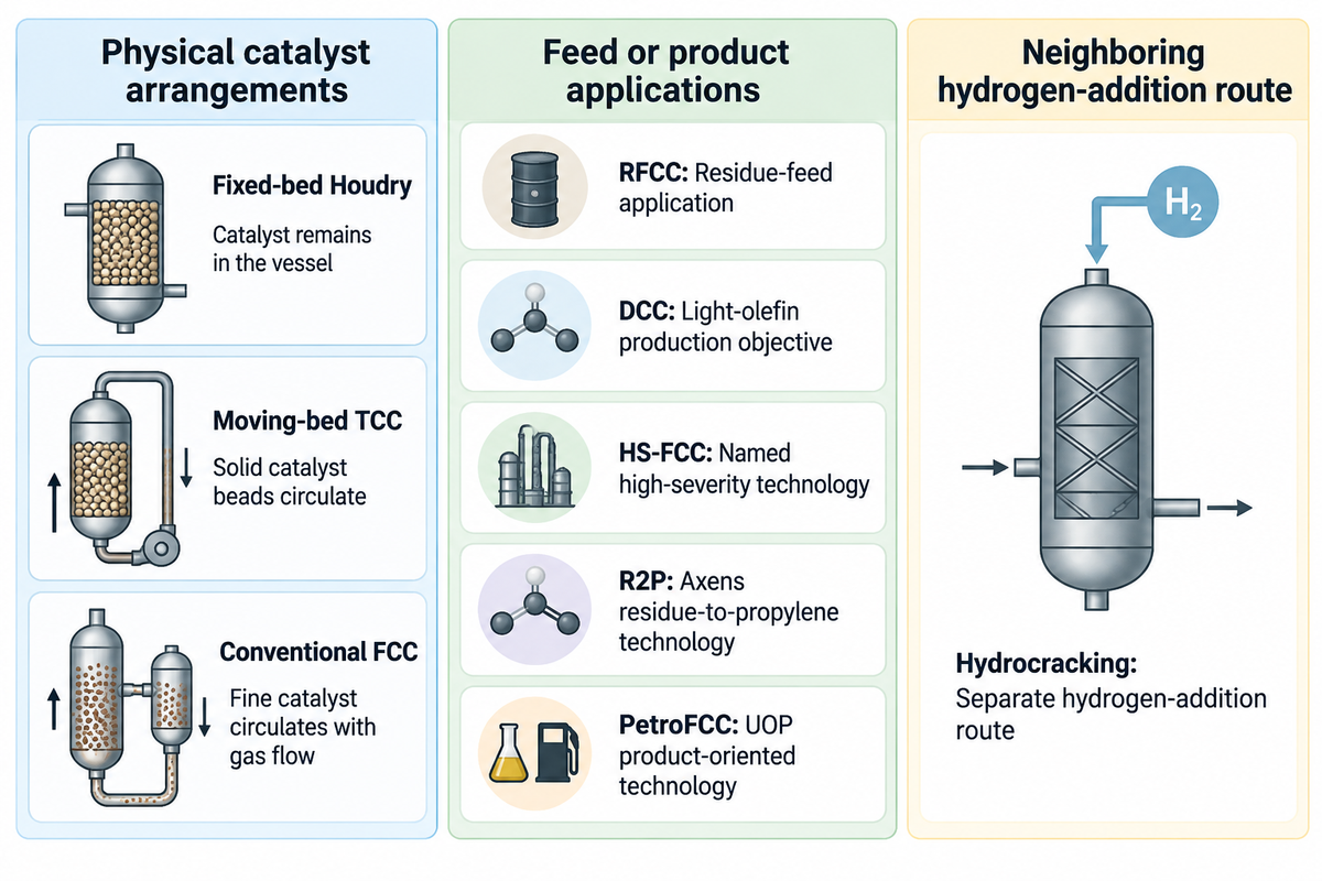
Catalytic cracking processes can be differentiated based on movement of catalyst and on what’s being converted or produced. Fixed, moving and fluidized beds describe the physical arrangement. RFCC and DCC describe applications or named technologies within the broader family of fluid-catalyst processes and, therefore, aren’t additional bed categories.
Two-Axis Cracker Map
The Two-Axis Cracker Map separates catalyst arrangement from feed and product objectives to allow buyers to classify a technology offer.
| Label | Classification level | What it tells the buyer | What still needs definition |
|---|---|---|---|
| Fixed-bed Houdry | Reactor arrangement | Catalyst remains in the vessel | Swing sequence and heat supply |
| Moving-bed TCC | Reactor arrangement | Solid catalyst beads circulate | Transport and regeneration layout |
| Conventional FCC | Fluidized catalyst arrangement | Fine catalyst circulates with gas flow | Feed assay and product basis |
| RFCC | Residue-feed application | FCC adapted to heavier residual feed | Metals tolerance and heat balance |
| DCC | Sinopec product-oriented technology | Light-olefin production objective | Named variant and product recovery |
| HS-FCC | Named high-severity technology | Down-flow reaction with short contact time | Feed quality and integrated recovery |
| R2P | Axens residue-to-propylene technology | Residue feed plus propylene objective | Residue properties and added equipment |
| PetroFCC | UOP product-oriented technology | FCC features aimed at light olefins or aromatics | Selected process features and feed |
| Hydrocracking | Separate hydrogen-addition route | Cracking with hydrogen and catalysts | Hydrogen supply and product slate |
Penn State’s Houdry description anchors the historical distinction of beds. Modern terms followed the relevant licensors’ terminology. For procurement, specify both the reactor arrangement and the feed and product objectives in the scope; a process name alone leaves the heat-recovery requirements undefined.
Fixed-Bed and Moving-Bed Catalytic Cracking
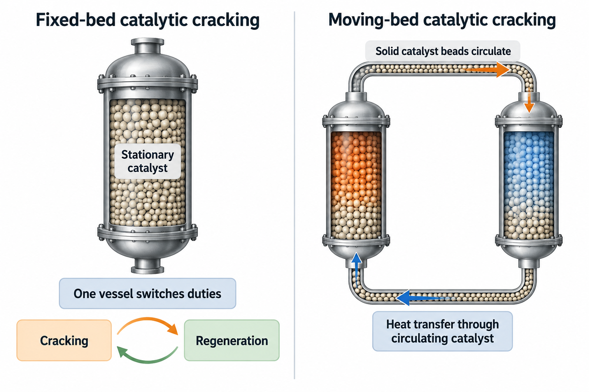
Fixed-bed catalytic cracking holds the catalyst stationary and switches between cracking and regeneration for each catalytic reactor. Moving-bed cracking circulates solid catalyst. Hot catalyst circulation supplies heat for the cracking reaction. However, the mechanical transport arrangement would affect heat loss and the complexity of the plant.
A fixed bed can support continuous plant output
Penn State exemplifies the Houdry process using three parallel reactors. In the historical example, gas oil enters a catalyst-packed vessel at 800°F, and coke deposits progressively reduce catalyst activity. After about 10 minutes of cracking, feed is switched to another reactor so the plant can continue processing oil.
In this historical example, the vessel undergoes five minutes of steam stripping to remove residual hydrocarbons from the catalyst, followed by about five minutes of catalyst regeneration to burn off coke. These steps explain the cyclic nature of one reactor while the wider installation can provide continuous output. The third reactor provides some allowance for delays in returning a vessel to cracking duty.
What is moving bed catalytic cracking?
Moving-bed catalytic cracking circulates solid catalyst beads between the two duties. In the historical Thermofor Catalytic Cracking process (TCC), movement of catalyst carries heat between the two duties. TCC is a catalytic process; its name does not make it thermal cracking.
Penn State’s moving-bed explanation covers bucket-elevator and gravity flow transport. The drawback of these historical systems was heat loss during transport. These historical systems show the development of modern cracking, but the mechanical arrangements of the systems shouldn’t be assumed to represent a current fluid-catalyst offer.
Fluid Catalytic Cracking: The Modern Base Process
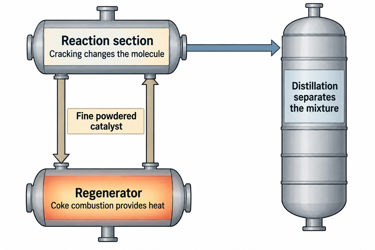
Fluid catalytic cracking passes a fine powdered catalyst between a reaction section and a regenerator. Gas flow makes the particles behave as a fluid and allows catalyst transport and rapid mixing with vaporized feed. Combustion of coke restores available catalyst surface and provides heat for the breakdown of large hydrocarbons into lighter products, including gasoline components.
“The coke on the spent catalyst is burned off, which reheats the catalyst to add heat to the FCC process.”
In a fluid catalytic cracker, regenerated catalyst comes back to contact the feed. Cracking changes the hydrocarbon molecule; the downstream fractionating column separates the mixture by distillation. The gasoline, gas, and cycle oil streams have different end points, and a cycle oil fraction may require further treatment to be used as diesel fuel.
Vacuum gas oil is a common FCC feedstock obtained after crude oil separation. In Penn State’s illustrative FCC description, the gas oil feed is preheated to about 300 degrees Fahrenheit and introduced into the reactor with steam. The chemical reaction and the separation train perform different functions: more reaction conversion can increase the load on downstream equipment. For more details on the reactor, regenerator and product streams, see our FCC process fundamentals.
This catalyst behavior is called fluid bed catalytic cracking. In Speight’s FCC overview, the finely powdered catalyst has a particle size on the order of 70μm and behaves like a fluid when mixed with the vaporized feed. Different internal flow patterns occur within vessels, and not all fluidized-solids processes use a catalyst.
RFCC: Adapting FCC to Residual Feed
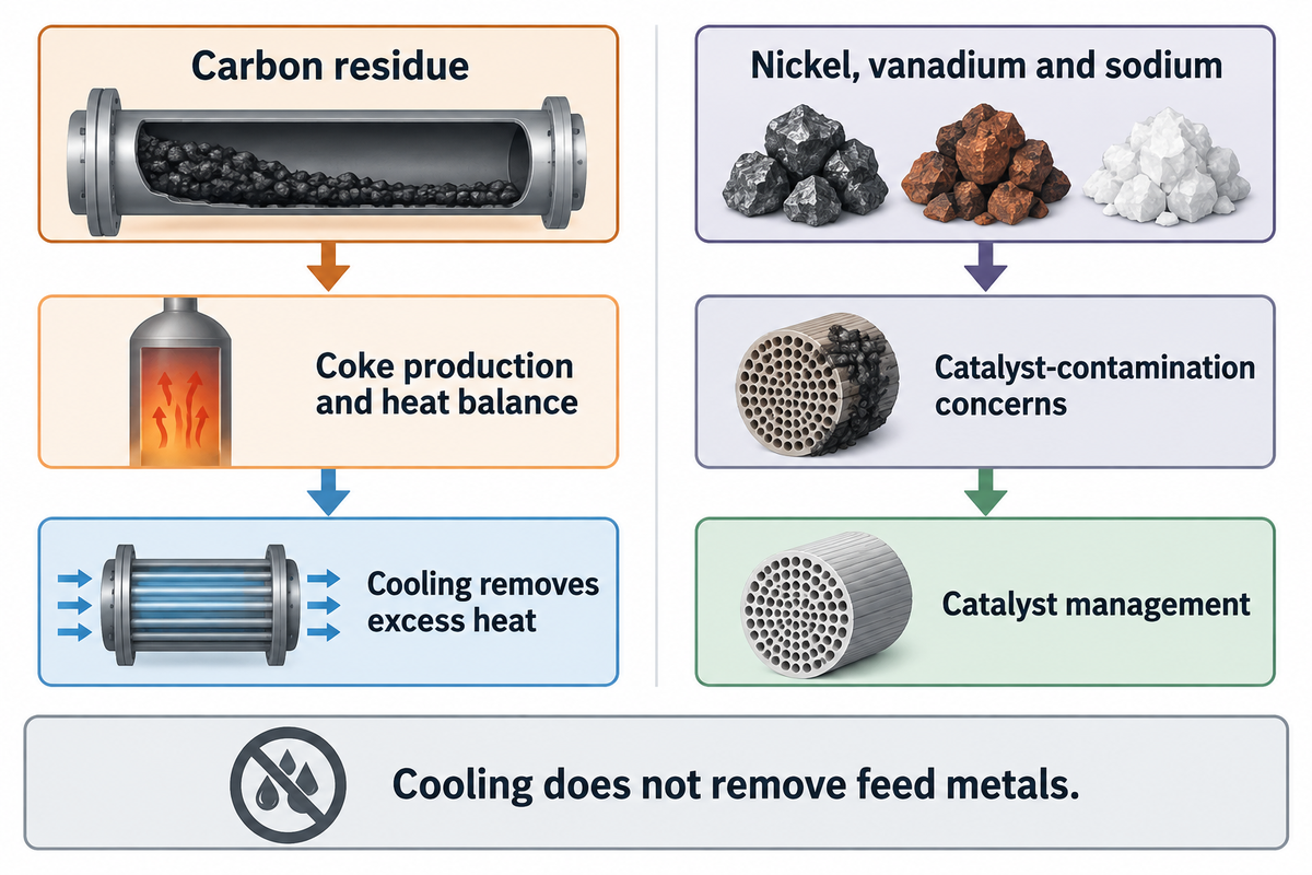
RFCC adapts fluid catalytic cracking to a residual feed that can increase the demands placed on catalyst management and regenerator heat removal. Carbon residue and feed metals are separate screening variables. A workable design must address carbon residue and feed metals, along with the required products.
UOP’s FCC-related processes datasheet targets its RFCC process at residual feeds above 4 wt% Conradson carbon. The datasheet describes a two-stage regenerator with catalyst cooling as the usual arrangement to manage the additional coke and heat.
Axens’ catalytic cracking overview uses different design context: single-stage regeneration is generally adequate for traditional distillate feeds or blends below roughly 2–3 wt% carbon residue, while residues above 3 wt% with high metals require more elaborate designs. These descriptions address their respective feed and technology ranges.
- Carbon residue: identifies a feed tendency relevant to coke production and the heat balance.
- Nickel, vanadium and sodium: add catalyst-contamination concerns that carbon residue doesn’t describe.
- Catalyst condition: affects the available activity and the management strategy for continued residue processing.
Cooling removes excess heat; it doesn’t remove feed metals. Proposals for heavier-feed flexibility require feed assay data and a catalyst management plan alongside the cooler load. The detail for formulation choices will be found in a different document on FCC catalyst composition and selection.
DCC and High-Propylene FCC: Product-Oriented Configurations
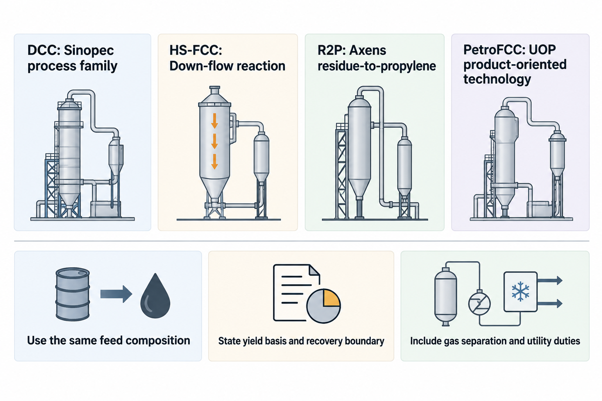
DCC technologies and other high-propylene FCC processes shift the product focus to light olefins. However, they retain distinct process identities. DCC is a Sinopec process family. Other licensors offer configurations for higher propylene product targets, so a comparison should be made with respect to feed, reaction design and product recovery rather than with the DCC process name in isolation.
In their presentation on DCC technology, Sinopec engineers Zhu and Shou describe the DCC platform and integrated variations. Proposers should verify the variant of the DCC technology offered as well as the recovery package, especially if the objective is to produce chemical products as opposed to a gasoline-led refinery slate.
Technip Energies’ HS-FCC description combines high temperature with down-flow reaction, short contact time and high catalyst circulation. Short contact time limits secondary reactions, while catalyst circulation provides heat and active surface for cracking. Axens names R2P for residue-to-propylene service, while UOP describes PetroFCC features aimed at light olefins or aromatics.
Relabeling all the processes as DCC conceals the differences in reactor design, feed, and licensing scope.
Compare
- Use the same feed composition.
- State the yield basis and recovery boundary.
- Include gas separation and utility duties.
Avoid
- Substituting one licensed name for another.
- Treating reactor yield as shipped product.
- Assuming severity changes need no hardware.
For the plant manager, the important consideration is how much on-spec propylene is available at the recovery outlet. For finance, that same limit sets the boundary of what separation equipment should be captured in the capital estimate. A higher rate of cracking is useful only within the limits of the complete system, including capacity and product quality.
Heat Recovery and Bottlenecks Across FCC Variants
FCC variants can cause a shift in the limiting duty among regenerator, gas recovery, fractionation and heat exchangers. A higher propylene target creates different questions from a higher residue feed. Each proposed change should be connected to the affected system and its capacity evidence before a reactor modification is the basis for the project budget.
Bottleneck comparison by process change
| Proposed change or symptom | System to compare | Required project input | Lead discipline |
|---|---|---|---|
| Higher residue carbon | Regenerator and catalyst cooler | Coke/heat balance and cooling duty | Process licensor |
| More feed metals | Catalyst management | Feed assay and catalyst condition | Process and catalyst specialists |
| More wet gas | Wet gas compressor | Gas rate, pressure and driver capacity | Process and rotating equipment |
| More recoverable propylene | Gas concentration and fractionation | Product specification and recovery basis | Process engineering |
| Higher unit throughput | Main fractionator | Vapor/liquid loads and pressure loss | Process and column specialists |
| Lost slurry heat recovery | Slurry exchangers | Duty, pressure-drop and fouling history | Heat-transfer and maintenance teams |
| Added catalyst cooling | Steam generation and users | Steam pressure and utility balance | Process and utilities teams |
| Changed coke combustion | Air supply and flue-gas system | Integrated pressure and flow balance | Process and environmental teams |
| Additional recovery equipment | Offsites and tie-ins | Utility capacity, plot space and outage scope | Project engineering |
As noted in the Axens propylene discussion, there can be hydraulic constraints which drive throughput to lower levels. The UOP catalyst cooler can generate either medium- or high-pressure saturated steam, while liquid product heat recovery is accomplished using slurry exchangers. Flue gas heat recovery and carbon monoxide handling are part of a different circuit, and these duties shouldn’t share one generic exchanger specification.
In Gary Martin’s 2016 revamp example, increasing feed from 33,500 to 40,000 b/d and conversion from 78.5 to 81.8 vol% is described. The wet gas compressor is driver-limited in this example. Conducting an isolated reactor-capacity study would leave a major constraint unaddressed downstream.
Martin assesses the integrated pressure system, consisting of the air blower, regenerator, fractionator and compressor. The case presents an interesting budgeting lesson. Retained equipment can determine the feasible expansion, even if the reaction section has headroom for changes. Therefore, procurement should request the bottleneck basis with the proposed scope and finance should evaluate alternatives on the basis of the same throughput and conversion assumptions.
Petroleum Cracking Routes: Catalytic and Thermal Cracking
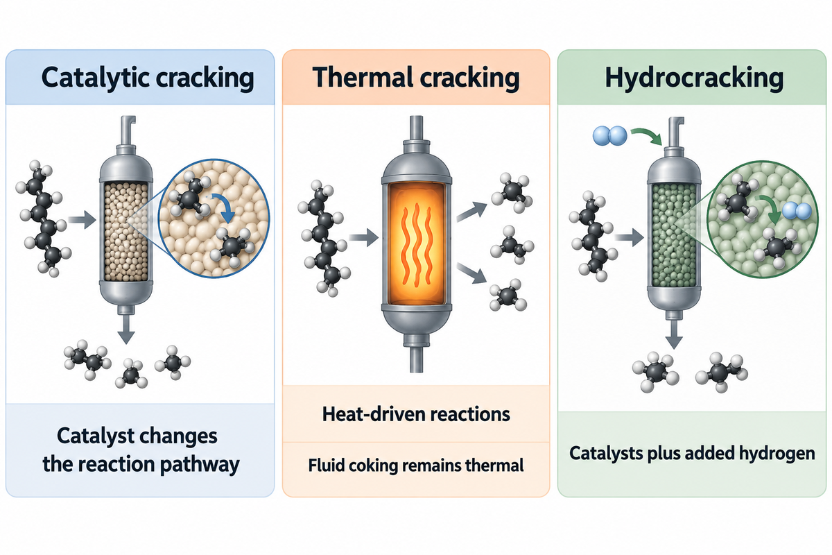
Catalytic cracking and thermal cracking employ different reaction routes to convert heavier hydrocarbon feed to smaller molecules. Catalytic cracking uses a catalyst without the hydrogen-addition scheme of hydrocracking. Thermal routes depend on heat-driven reactions, and therefore their product objectives should be evaluated separately compared to FCC catalyst-bed arrangements.
What are the differences between catalytic cracking and thermal cracking?
Catalytic cracking uses a catalyst to alter a reaction pathway and product selectivity, while a thermal cracking process relies on heat without that catalytic function. The reaction chemistry and differences are explained in Penn State’s conversion-process overview. Both can break larger molecules into smaller molecules; however, the feed and desired products determine which refining process is applicable to the project.
Catalytic routes
- FCC circulates fine catalyst.
- RFCC addresses residual-feed requirements.
- Hydrocracking adds hydrogen and has separate process requirements.
Thermal routes
- Steam cracking targets petrochemical olefins.
- Coking converts heavy feeds and produces coke.
- Fluid coking uses fluidized solids without becoming FCC.
The EIA’s refining definitions distinguish fluid coking from catalytic cracking, and describe the hydrogen requirement of the hydrocracking process. For an olefin project utilizing lighter feed, see the naphtha steam cracking guide. For hydrogen-based upgrading, see hydrocracking and hydrotreating. A kerosene, distillate or fuel oil objective calls for a completely different product comparison from an objective centered around gasoline and propylene.
Technology Licensors, Equipment Suppliers and Revamp Scope

A refining technology licensor defines the licensed process basis. Engineering contractors integrate the project. Equipment and maintenance suppliers deliver their scopes. The cost to revamp an FCC unit follows these boundaries. Two quotations can differ in retained equipment, utility changes and outage work while appearing to promise the same feed capacity or product target.
Ed Palmer’s front-end scope discussion relates revamp planning to equipment condition, offsites and utilities. Comparing only reactor package prices leaves other project costs outside the scope of the decision.
Separate the deliverables before comparing prices
| Work package | Include in the comparison | Primary interface |
|---|---|---|
| Process technology | Named process, feed range and product basis | Licensor and refinery owner |
| Retained equipment | Capacity assessment and required modifications | Engineering contractor |
| Gas recovery | Compression, separation and product specification | Process and equipment teams |
| Heat exchangers | Thermal duty, materials and mechanical scope | Designer and manufacturer |
| Utilities and tie-ins | Steam, cooling and connection requirements | Site project team |
| Maintenance access | Bundle dimensions, weight and removal space | Maintenance equipment supplier |
In its 2022 investigation release, the U.S. Chemical Safety Board noted that portions of many older U.S. FCC units had been revamped by multiple technology licensors. Trace the design history of each affected section before assigning new work; the original process name may not describe every subsequent modification.
For a refinery owner deciding how to refine a heavier feed, a good commercial comparison is a common scope with exclusions visible. Equipment with a lower price can still require more site work.
Maintenance Interfaces and Project Handoff
Maintenance handoff connects the process duty to the physical exchanger and the equipment to service it. Thermal performance and tube-bundle dimensions and access are additional inputs. A supplier can select handling or cleaning equipment only when the project inputs match the actual exchanger, rather than a general label such as RFCC or cat cracker.
In a 2008 article by Grace engineers David Hunt, Bill Minyard and Jeff Koebel, one refiner needed three slurry-exchanger cleanings within ten weeks. Each cleaning caused a feed-rate reduction. The authors present the interrelation between heat-transfer duty and the exchanger’s operating history with regard to fouling.
The inquiry for the cleaning equipment needs to address the deposit condition and access arrangement. Process engineers assess why deposits formed and quantify the lost heat-recovery duty. Bundle handling covers mechanical removal of the tube bundle. The reported case wasn’t simply about the cost of the cleaning equipment. The production loss was due to repeated loss of exchanger availability.
The public scope sheet for API 660 lists mechanical design, material selection, fabrication, inspection and testing requirements for specified shell-and-tube heat exchangers used in petroleum refining. The project requirements must still define the service and equipment type.
Sinopec’s DCC offering and the process technologies of UOP and Axens involve process licensing. At BOSHIYA, our focus is on tube-bundle handling and cleaning equipment, rental and service support. When requesting tube bundle extraction equipment and exchanger cleaning equipment for the planned outage, please send us the dimensions, weight of the bundle and deposit condition, access constraints and your planned service scope.
Maintenance handoff
Carry the actual exchanger duty and access requirements into the maintenance package.
Our refinery equipment services address the maintenance scope through handling and cleaning equipment rental and service support.
Frequently Asked Questions
What are the three types of cracking in petroleum refining?
This guide compares thermal cracking, catalytic cracking and hydrocracking as three reaction routes. Hydrocracking also uses catalysts, with added hydrogen distinguishing its process requirements. Within non-hydrogen-addition catalytic cracking, the historical reactor classification is fixed-bed, moving-bed and fluidized-bed. Fluid coking illustrates the difference: it uses fluidized solids but remains a thermal process.
What are the two main types of cracking?
The broad distinction is thermal cracking and catalytic cracking: heat drives the former, while a catalyst changes the reaction chemistry of the latter. Hydrocracking adds hydrogen and is usually discussed separately because of its process requirements. Fixed-bed, moving-bed and fluidized-bed instead describe catalyst arrangements, so those labels answer a different classification question.
Which catalyst is used in catalytic cracking?
Modern FCC uses fine catalyst particles containing zeolitic active components and a supporting matrix. Fresh catalyst replenishment and routine coke removal address different aspects of catalyst condition. Coke removal restores available active surface, while contaminant accumulation requires separate management; selecting a formulation requires the feed and product objectives, not just the process acronym.
Is hydrocracking a type of catalytic cracking?
Hydrocracking is catalytic in a chemical sense, but petroleum industry classifications commonly treat it as a separate process because it uses added hydrogen. This guide therefore compares it as a neighboring route, outside the main FCC-family taxonomy.
Are RFCC and DCC interchangeable?
No. RFCC describes residue-feed processing within the fluid-catalyst family, while DCC identifies a particular technology family directed toward light olefins. A residue-processing project may also target propylene, but that combination still requires a named process design, feed basis and recovery scope. Compare the catalyst and heat-management requirements, then the downstream gas and product-recovery duties. Shared use of a fluidized catalyst doesn’t make the reactor internals, regeneration arrangement or product guarantees interchangeable. The technology licensor’s defined scope determines what’s included in an actual offer.
References & Sources
- Penn State: Houdry catalytic cracking.
- Penn State: Moving-bed catalytic cracking.
- U.S. EIA: Fluid catalytic cracking process explanation, 2012.
- Gary Martin: FCC unit revamps at minimum cost, 2016.
- Penn State: Catalytic conversion processes overview.
- U.S. EIA: Refinery process definitions.
- Ed Palmer: Accurate front-end scope definition, 2014.
- U.S. Chemical Safety Board: Husky Superior investigation release, 2022.
- Hunt, Minyard and Koebel: Minimising FCC slurry exchanger fouling, 2008.
- American Petroleum Institute: API 660 public scope sheet.