Get in Touch with BOSHIYA

Fluid Catalytic Cracking (FCC): Complete Process Guide [2026]

Fluid Catalytic Cracking (FCC): Process Fundamentals, Key Equipment, and Refinery Economics
Contents
show
Fluid catalytic cracking is the key mechanism – and the namegiving unit – that allows today’s refineries to transform a single barrel of crude into close to a half a barrel of motor gasoline. As of 2024, United States FCC fresh-feed capacity stood at around 5.49mn barrels per stream day – about 28 percent of US total crude distillation capacity. Globally, an estimated 400 continuous utility FCC units are configured in leading petroleum processing facilities to convert at least one third of all crude into various distillate products. Every worldscale gasoline running refinery has at least one cat cracker.
This paper covers the fundamentals of the FCC process, key equipment packing material elements, catalyst chemical properties, product yield profiles, economics of the FCC unit and technological reforms happening under pressure of decarbonization – for refinery engineers, project managers and EPCs deliberating FCC scope of work and prep for turnarounds.
What Is Fluid Catalytic Cracking? Hydrocarbon Conversion and Refinery Role
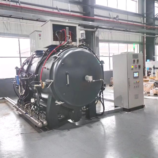
Fluid catalytic cracking (FCC) is a refinery conversion process that breaks large hydrocarbon molecules in heavy gas oil and vacuum gas oil into shorter-chain, higher-value products — primarily FCC gasoline, liquefied petroleum gas (LPG), and light cycle oil (LCO) — using a fluidized zeolite catalyst at high temperature (480–550 °C) without added hydrogen. It is the primary gasoline-production unit in most modern oil refineries and the backbone of global petroleum products output.
What Does FCC Mean in a Refinery?
In common oil refinery parlance, “FCC” (fluid catalytic cracking) refers both to the process itself and to the physical unit which runs the process – colloquially known as the “cat cracker. Zeolite catalyst particles (fluidized catalytic cracking, not fixed bed) effect the carbon-carbon bond scission of long-chain hydrocarbons in the feedstock. Circulating catalyst flux between the reactor and regenerator makes the process self-sustaining in terms of energy balance, with the oxygen from coke accumulation in the regenerator providing thermal energy to supply the endothermic cracking reactions occurring in the riser.
In contrast to hydrocracking, FCC requires no hydrogen. This makes the process the higher throughput, lower capital-intensity option for refineries whose primary product output is gasoline and light olefins, rather than middle distillates. Feedstocks to FCC units also directly influence the supply capabilities of the petrochemical industry – every LPG-rich FCC unit is a potential propylene provider to downstream polymer sectors.
Boshiya provides specialist oil refinery process equipment for turnaround and maintenance work on the FCC unit and associated heat exchange systems — including bundle pullers, tube bundle cleaners, and extraction tools that keep FCC feed preheaters and product coolers running between outages.
Feedstock
Vacuum Gas Oil (VGO)
Riser Temperature
480–550 °C
Reactor Pressure
~1.72 bar
Cat-to-Oil Ratio
~5:1 by weight
Primary Product
FCC Gasoline (40–62 vol%)
Run Length
2–3 years continuous
How the FCC Process Works: Cracking Hydrocarbons in the Riser Reactor and Regenerator Cycle
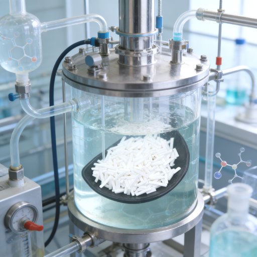
How Does a Fluid Catalytic Cracking Unit Work?
A single FCC unit functions as a continuous re-circulatory loop between two different vessels – the riser reactor and the regenerator – with the catalyst circulating through a circulation rate in excess of 55k tonnes per day in a world-scale plant. Each stage is outlined here:
Stage 1 – Cracking in the riser. The preheated feedstock (example VGO, 315-430 C) interacts with a flow of hot, pure and regenerated catalyst particles at the bottom of a vertical riser reactor. The particles vaporize the incoming hydrocarbon streams on contact and the vaporized mix of hydrocarbon and entrained catalyst particles made up thereof works its way upward in the riser at 480-550 C. The high temperature (endothermic) cracking reactions break down the large molecules into smaller hydrocarbons – gasoline-range hydrocarbons, with 12 carbons or less, and LPG-range hydrocarbons, with 3-4 carbons. Riser residence time: 2-4 seconds.
Stage 2- Separation. Cyclone separators placed over the top of the riser strip entrained catalyst particles from the cracked product vapor. Cracked hydrocarbons are circulated to the main fractionator for distillation into product fractions. Spent catalyst was dumped toward the stripper section located beneath. Down-scaled modern riser-based FCC designs replaced the dense-phase fluidized bed reactor employed in earlier units by converting the reactor vessel into dedicated separator and stripper housings, substantially improving selectivity and greatly lowering the over-cracking rate.
Stage 3- Stripping. Residual hydrocarbon vapor is stripped from the spent catalyst surface using steam prior to moving the catalyst to the regenerator. By limiting stripper section inefficiencies, catalyst coke yields can be reduced while simultaneously increasing the volume of the more valuable saleable liquid product – operational targets regular ranging optimization strategies.
Stage 4- Regeneration. Spent catalyst – containing 0.3-1.5 wt% catalyst coke from the cracking reaction – enters the regenerator. Catalyst coke is burnt off at roughly 715 °C and 241 kPa, reducing the residual catalyst coke content (CRC) on regenerated catalyst (RC) to <0.1 wt% in contemporary single-stage full-burn units. High-temperature, highly-energized regenerated catalyst then returns to the riser bottom, providing the heat that sustains the endothermic cracking process, and effectively recycles the catalyst.
Engineering Note — Riser & Regenerator Design Parameters
Feedstock preheat: 315–430 °C | Riser entry: ~535 °C | Riser operating pressure: ~1.72 bar | Cracking residence time: 2–4 seconds | Cat-to-oil ratio: 4.66–5.0 kg catalyst / kg feedstock | Single-stage full-burn regenerator temperature: 650–750 °C, with modern resid-processing units reaching 732 °C | Regenerator operating pressure: ~241 kPa. Over-cracking indication: Operation at the upper range of residence time or riser temperature converts otherwise producible C3+ liquid product back into dry gas (methane, ethane). Dry gas output rising above ~4 wt% of feed indicates riser is processing too hot or long.
Downstream of the riser, the primary main fractionator distills the cracked product vapor into: FCC gasoline (naphtha, C5-390 F fraction), light cycle oil (LCO, the diesel-range portion), heavy cycle oil (HCO), clarified slurry oil (CSO), a second overhead gas fraction, comprising LPG and dry gas, plus other separate downstream treating and blending facilities for each distinct product fractions.
Key Components of the FCC Unit: Riser, Stripper, Cyclones, and Fractionator
A complete FCC unit comprises five key process segments. Variance in specific designs, names, and procedures required according to licensor (UOP/ Honeywell, Shell Global Solutions, ExxonMobil), and whichever feedstock conventionally VGO versus RFCCs of atmospheric or vacuum residues, but all modern units have a common set of elements:
| Component | Function | Specification Range | Material |
|---|---|---|---|
| Riser Reactor | Catalytic cracking of VGO feed; produces cracked product vapor | 20–50 m tall; upflow; 480–550 °C; 2–4 sec residence time | Carbon steel + erosion-resistant refractory lining |
| Regenerator Vessel | Burns coke from spent catalyst; restores catalyst activity; supplies heat to riser | 650–750 °C; 241–380 kPa; single-stage or two-stage | Carbon steel + castable refractory; high-alloy internals |
| Cyclone Separators | Disengages entrained catalyst particles from cracked product vapor; 2-stage typical | Particle cut: 10–150 µm; primary + secondary stages; pressure drop monitored | High-alloy erosion-resistant steel |
| Stripper | Steam-strips residual hydrocarbons from spent catalyst before regeneration | Baffled column; steam injection at base; residence time 1–3 min | Carbon / low-alloy steel |
| Main Fractionator | Separates cracked products by distillation into LPG, naphtha, LCO, HCO, slurry | Multiple draw trays; quench-cooled bottom; full pressure drop balance required | Carbon steel; stainless steel in high-corrosion zones |
Catalyst inventory is effectively a sixth critical process component — and in day-to-day operations, the one most engineers focus on. A 75,000 bbl/day FCC unit holds approximately 150 tonnes of catalyst inventory and circulates roughly 55,900 tonnes of catalyst per day between reactor and regenerator — a continuous high-velocity erosive service that places demanding requirements on catalyst separator and cyclone design. Catalyst particles measure 10–150 µm in diameter (average 60–100 µm), with bulk density 0.80–0.96 g/cm³ and zeolite content 15–50 wt%.
Boshiya Engineering Framework
The 5-Variable FCC Performance Matrix
FCC operation relies on five effective variables acting in harmony – determining the output of each requires precise simultaneous adjustment of these five parameters:
- Feedstock Quality – API gravity, CCR, Ni and V contents, S and N determine the highest limiting conversion achievable before the first catalyst particle is contacted.
- Catalyst Activity – Fresh catalyst add rate, equilibrium catalyst (E-CAT) activity (MAT), zeolite surface area and Ni/V loading on E-CAT define cracking selectivity per pass.
- Riser Outlet Temperature -Higher outlet temperature increases conversion but accelerates thermal cracking to dry gas; their optimal window for VGO feeds are on the order of 520–540 °C riser outlet.
- Residence Time – Short residence times (2-3 sec) maximize the C5+ liquid yield; too long residence times (>4 seconds) promote excess cracking to dry gas and H2 at the expense of gasoline.
- Regenerator Effectiveness – A CRC below the 0.1 wt.% range is necessary to fully recover activity in one pass using a single-stage design; the addition of a two-stage regenerator raises activity recovery to the 0.05 wt.% range CRC, adding 1-2 ten-point increment to the conversion per pass.
Framework developed by the Boshiya engineering team. May be cited with attribution.
FCC Catalyst: Zeolite Chemistry, Catalysis, and Regeneration
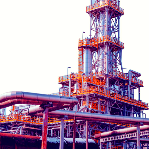
Unlike a bulk mineral, FCC catalyst is a complex precision-built composite. Its active component is a microcrystalline aluminosilicate zeolite, most often Ultrastable Y zeolite (USY), which is then loaded into a silica-alumina matrix with additives to improve octane, passivate metals, and destroy SOx. Catalysis takes place at the Brønsted acid sites inside the zeolite micropore network byprotonating and providing subject to hydrogen the delivering carbenium-ion catalysis pathway.
Principal zeolite types in commercial FCC catalysts:
- USY (Ultrastable Y Zeolite) – The main cracking component in practically every FCC catalyst formulation is ultrastable Y. It provides the high density of acid sites needed for both high conversion and good gasoline selectivity. Typical zeolite loadings are 15-50 wt% of a commercial formulation, depending on target activity. Compared to convention NaY, USY has greater hydrothermal stability in the high-temperature environment of the FCC catalyst regenerator (~715 °C steam-laden flue gas contact).
- ZSM-5 – Is incorporated as an octane-boosting additive at low levels (1-5 wt% of total catalyst). It promotes skeletal isomerization of low-octane linear paraffins and olefins, raising FCC gasoline research octane number by 1-3 numbers while raising overall Propene production for a petrochem applications.
Catalyst deactivation in an FCC operation occurs via three different mechanisms; misdiagnosing the cause of the catalyst loss results in inappropriate corrective actions:
1. coke- The reversible accumulation of hydrocarbon coke deposits on zeolite surface and acid sites. These are burned off in the regenerator at 650-750 C, fully recovering category activity function of the zeolite present. Using fully optimized one-stage full-burn regenerator designs, this reduces residual catalyst coke (CRC) levels from old-minumum (pre-modern) range of 0.3-0.5 wt% down to less than 0.1 wt%; two-stage regenerator designs can be optimized to a 0.05 wt% CRC range.
2. Thermal and hydrothermal sintering – Semi irreversible, the loss of surface area and pore structure due to hydrothermal conditions that result within the steam containing environment created when carbon is burned off in the presence of water vapor at 700+ C. In simplest terms, the water released when the hydrogen is removed from coke creates a steam-rich environment that results in hydrothermal destruction of the catalyst micropore architecture. Two-stage regenerator designs limit this to the lower temperature first stage to prevent this outcome.
3. Metals poisoning by nickel and vanadium- Largely irreversible. Ni and V deposit from feed contaminants onto the fresh catalyst surface and cannot be washed out by catalyst regeneration. It is single most important deactivation mechanism in the context of processing high-metals feeds. Ni catalyzes the non-selective dehydrogenation reactions- leading to sharply increased dry gas and hydrogen yields, at the expense of liquid products. V catalyzes attack on the zeolite lattice structure itself, accelerating undesirable permanent loss of crystallinity and activity. Standard mitigation measures include: (a) antimony or bismuth passivating additives for Ni;(b) vanadium traps added to catalyst blend; (c) fresh catalyst make-up rate controlled to maintain acceptable E-Cat activity.
As presented in their seminal survey of FCC catalysis (Chem. Soc. Rev., 44, 7342-7370, 2015-Chem.Soc.Rev. is the most cited chemical review article of all time), Emiel T.C. Vogt and Bert M. Weckhuysen from Utrecht University documented how zeolite catalyst technology revolutionized FCC performance post its industrial adoption, and identified metals deactivation by nickel and vanadium as the unresolved fundamental challenge that persists as the greatest industry wide constraint to catalyst lifetime. That publication remains the standard academic reference on why regeneration corrects coking deactivation, but cannot counter metals poisoning induced permanent catalyst activity deterioration.
Vogt, E.T.C. & Weckhuysen, B.M., “Fluid catalytic cracking: recent developments on the grand old lady of zeolite catalysis,” Chem. Soc. Rev., 2015, 44, 7342–7370.
Operator takeaway #1: catalyst regeneration does not restore catalyst activity to fresh catalyst levels. This is a widely held misconception by young FCC engineers starting out on the job. Coke deactivation is fully reversible; deactivation from hot sintering and metals accumulation is not. Fast apparent catalyst activity erosion on the E-Cat is invariably a metals effect indication, not a regenerator fault.
FCC Products and Typical Yield Distribution
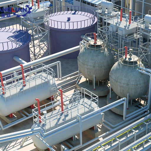
Yield distribution in FCC is not fixed. It varies according to feed stock quality parameters (API gravity, CCR, contamination metals), operating parameters (riser temperature, conversion level), and the catalyst used (USY activity level, ZSM-5 level). This depicts the typical FCC yield pattern of API 33.5 clean waxy gasoil feed processed in a modern zeolite catalyst FCC unit at 80% conversion.
40–62%
FCC Gasoline yield (vol%)
15–20%
Light Cycle Oil yield (vol%)
4–8%
Coke yield (wt%)
3–5%
Dry Gas yield (wt%)
89–94
FCC Gasoline RON (typical range)
| Product Fraction | Typical Yield | Key Characteristic | Downstream Disposition |
|---|---|---|---|
| FCC Gasoline (C5–390 °F naphtha) | 40–62 vol% | High octane (RON 89–94); high sulfur; high olefins | Motor fuel blend pool after FCC naphtha hydrotreater (sulfur removal) |
| LPG / Light Olefins (C3–C4) | 10–20 vol% | High propylene content (4–8 vol% of feed); butylene to alkylation | Propylene → petrochemicals; butylene → alkylation unit for high-octane gasoline blendstock |
| Light Cycle Oil (LCO) | 15–20 vol% | Diesel boiling range; low cetane (high aromatics); high sulfur | Diesel blendstock after hydrotreating; partial aromatic saturation required for ULSD |
| Clarified Slurry Oil (CSO) / HCO | 5–8 vol% | High aromatic content; high catalyst fines; low-value fraction | Fuel oil blend, carbon black feedstock, or recycle to riser |
| Coke | 4–8 wt% | Deposited on catalyst; burned in regenerator | Not a saleable product; provides heat for cracking reactions |
| Dry Gas (C1–C2: methane, ethane) | 3–5 wt% | Low value; signals over-cracking when above 4–5 wt% | Refinery fuel gas header |
At the end of the gasoline yield spectrum (62 vol%), is a high-activity zeolite catalyst (similar to XZ-25 zeolite) at 80% conversion on a clean waxy gasoil feed. Feed stocks of inferior quality with elevated metals loading or high CCR yields less gasoline and greater quantities of coke. Fields of refineries with petrochemical production orientation (such as ethylene- propylene producer) – using Deep Catalytic Cracking (DCC) or High Severity FCC configurations- ampute their gasoline yield and focus on maximizing propylene, which at the excess severity levels produced can make up 2040% of net feed+ as the predominant product.
High-octane content of FCC gasoline (RON 89–94) is a direct consequence of catalytic cracking chemistry. Carbenium-ion catalyzed cracking chemistry favors formation of branched paraffins and aromatics (both high-octane), while thermal cracking gives increased quantities of linear paraffins, resulting in deliveringan average only ~25% gasoline at lower RON products. This is the reason the industry phased out thermal in the 1940s, in favor of catalytic systems.
FCC vs Hydrocracking vs Thermal Cracking: A Technology Comparison
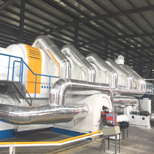
Three heavy petroleum upgrading processes dominate in the modern refining environment: fluid catalytic cracking, hydrocracking and thermal cracking (primarily through delayed coking). They all each operate by a different chemistry, and realize different product strategies. Their relative implementation is the most significant capital allocation decision in a refinery configuration.
What Is the Difference Between Fluid Catalytic Cracking and Hydrocracking?
Chemistry is the critical differentiator, FCC is a carbon-rejection technology: it breaks the large heavy molecules with high thermal severity over a zeolitic catalyst, rather than adding hydrogen, thus increasing the coke burnoff in the regenerator and saving hydrogen. Hydrocracking is a hydrogen-injection technology: it adds hydrogen to heavy petroleum feedstocks by reacting them with high purity H over a bifunctional catalyst (acid + hydrogenation). This distinction cascades through every downstream variable — product quality and sulfur specification, operating pressure, hydrogen consumption, capital cost, and environmental compliance profile.
| Dimension | FCC | Hydrocracking | Thermal Cracking (Delayed Coking) |
|---|---|---|---|
| Chemistry | Carbon rejection; zeolite acid catalysis | Hydrogen addition; bifunctional catalyst | Thermal (non-catalytic); carbon rejection |
| Primary feedstock | Vacuum gas oil, heavy gas oil (340–565 °C cut) | VGO, FCC cycle oils, coker gas oil, deasphalted oil | Atmospheric residue, vacuum residue, tar sands bitumen |
| Primary products | Gasoline / FCC naphtha (~40–62 vol%), LPG, LCO | Middle distillates: diesel, kerosene; low-sulfur naphtha | Petroleum coke, coker naphtha, coker gas oil (for further upgrading) |
| H₂ requirement | None | High — 400–2,000 scf/bbl; requires dedicated hydrogen plant | None |
| Operating pressure | Low (~1.7–2.4 bar) | High — fixed bed: 100–200 bar; ebullated bed: up to 250 bar | Moderate (~3.5–6 bar) |
| Product sulfur | Moderate — FCC naphtha and LCO require hydrotreating for ULSD compliance | Very low — produces on-specification ULSD diesel directly | High — coker naphtha is high-sulfur and high-olefin; requires hydrotreating |
| Capital cost (relative) | Moderate — $300M–$1B+ world-scale ⚠ | High — H₂ plant + high-pressure reactor metallurgy adds significant premium over FCC | Lowest among the three for new-unit construction |
| Best suited for | Gasoline-focused markets; no ULSD requirement; moderate feed quality; lower capex budget | Diesel-demand markets; strict ULSD regulations (IMO 2020, EPA Tier 3); high-sulfur or high-aromatic feeds | Residue disposal; bitumen / heavy crude upgrading; lowest-cost entry to conversion |
When refineries integrate FCC with hydrocracking, the most typical scheme utilizes mild (100-200C) hydrocracking of FCC cycle oils (LCO and HCO) to upgrade bottom-of-the-barrel into onspecification diesel blends. Petrochemical-integrated refineries expand this approach: hydrocracking feed using upgraded, priorzeered, and pre-refined VGO (ultra-high recovery, ultra-low integration) to maximize gasoline yield and sustain FCC unit feed rate while balancing the bottoms ratio.
FCC Advantages
- No hydrogen required — lower capital and operating cost
- High-octane FCC gasoline (RON 89–94)
- Continous operation – catalyst regenerated in-situ with no process shutdown
- Tunable severity — conversion adjustable 60–85%+ by operating changes
- Petrochemical integrated configurations produce up to 40% light olefins (HS-FCC, DCC)
FCC Limitations
- LCO is low-cetane diesel; marginally hydrotreating upgrade (ULSD)
- Alkylosomes & aromatic blocks cannot be cracked – slurry oil fraction encounters limited upgrading pathways
- Feed metals sensitivity — Ni/V accelerate permanent catalyst deactivation
- Regenerator flue gas requires SOx/NOx emissions controls
- Continous fresh catalyst makeup cost is a major operating expense
Technology Selection Decision Rule
Choose FCC when the target product is maximum gasoline and LPG, the feed is moderate-quality VGO with manageable metals, ULSD compliance for LCO is acceptable via downstream hydrotreating, and the capital budget does not support a high-pressure H₂ plant. Choose hydrocracking when the primary target is ULSD diesel or jet fuel, environmental regulations demand low-sulfur products from the conversion unit itself, and the feed contains high aromatics or metals that benefit from H₂-stabilized catalysis. Many world-scale refineries run both technologies in tandem, capturing added value from their complementary product slates.
FCC Unit Cost, Capital Investment, and Refinery Economics
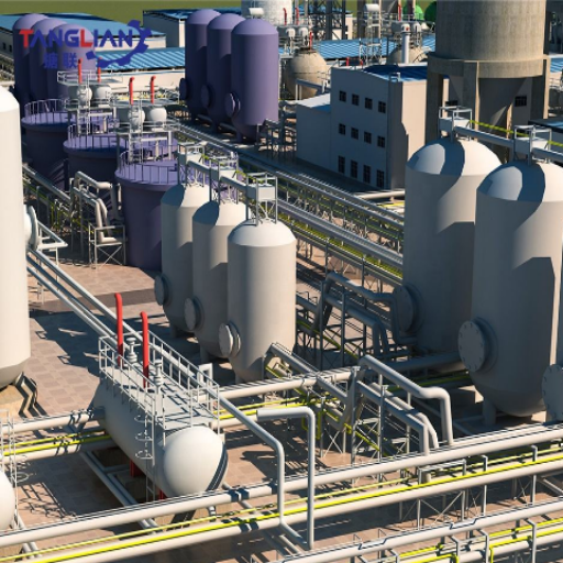
A typical world-scale FCC is 75,000-125,000 bbl/day and costs 300 million to over 1 billion US dollars to construct depending on throughput, make-up requirements, residue feedstock type (conventional VGO or resid FCC/ RFCC), location and environmental/regulatory service scope. Residue FCC processing feed stocks with elevated metals and CCR (diesel, vacuum residue) can attract a premium on heat recovery boiler, wet gas scrubber & electrostatic precipitator scope to a GCV.
Global FCC market for equipment, catalysts, and services was valued at approximately $7.67 billion in 2025 and is expected to reach $9.33 billion by 2031 at a CAGR of 3.32% indicating it is neither a stranded nor declining technology but one which will grow by attracting new sources of refinery capacity, primarily within Asia, and growing sectors of mechanical and petrochemical integration.
Operating margin for US Gulf Coast FCC units was down 15% in 2024 compared to the previous year as US gasoline demand was running 5.6% below pre-pandemic baselines in the mid-year of 2024. Consequently, leading EPA-mandated operating priorities in order to have greater flexibility in the choice of feedstocks and metering to avoid Category 3 AEO status are prevailing as the investment appetite for a new FCC unit continues to shrink in favor of increased efficiencies in existing units.
FCC-related heat exchangers are some of the dirtiest services in petroleum processing — asphaltene fouling in feed/effluent preheat exchangers, ammonium chloride salts in main column overhead condensers, and catalyst fines in slurry product coolers. Planned heat exchanger maintenance in refinery and petrochemical plants — tube bundle extraction and cleaning at each turnaround — directly affects FCC unit conversion efficiency and run length. For refinery maintenance planning guidance, see also Boshiya’s coverage of refinery turnaround cleaning procedures and FCC heat exchanger bundle extraction during turnaround.
Pro Tip — The Cat-to-Oil Economics Lever
Cat-to-oil ratio is the quickest-responding variable to set for FCC conversion and conversion drives the revenue split between high-value gasoline / LPG and low-value LCO/ Slurry. A 1 unit change in cat/oil ratio (eg 6:1 7:1) causes an increase in conversion of 1.5-3% points. The cost higher coke yield leads to more regenerator air requirement and utility spend.
The perfect cat/oil ratio is the optimum compromise between unit heat balance, air blower capacity and product value hierarchy at the time. There is no general rule – it must be modeled each time for each unit and feed.
The Future of FCC: Decarbonization, Bio-feedstocks, and Clean Fuel Trends
Energy transition has not abolished fluid catalytic cracking. More precisely: it has reshaped the streams fed into FCC units, as well as the products those units will be asked to produce by 2030. Today, three bodies are in charge:
RISING ↑
Bio-feedstock co-processing. US Department of Energy BETO-funded pilot testing by NREL demonstrated that co-processing fast pyrolysis bio-oils at 5% blend levels with conventional VGO produced “no significant change” in main product fractions (gasoline, LPG, distillates) compared to straight VGO operation. Minor penalties at 5%: slight increase in aqueous fraction and coke yield, manageable with existing regenerator capacity. Ketjen launched its ReNewFCC catalyst specifically engineered for bio-co-processing (product updated February 2026). Petrobras earmarked $1.5 billion for its BioRefining Program (2025–2029), prioritizing co-processing renewable streams in its existing FCC fleet. These are not pilot programs — they are capital-committed commercial deployments.
RISING ↑
FCC-to-petrochemicals integration. High-Severity FCC (HS-FCC) and Deep Catalytic Cracking (DCC) shift the product slate from gasoline toward light olefins — propylene, ethylene, butenes — with light olefins yields jumping from a conventional 14% to as high as 40% of feed under petrochemical configurations. China is projected to account for nearly 60% of global propylene capacity additions between 2024 and 2030, driving demand for high-severity FCC configurations across Asia.
ADAPTING →
Regenerator emissions under regulatory pressure. EU ReFuelEU mandates, EPA stack rules, and ICAO’s net-zero 2050 aviation commitment are driving refineries to evaluate CO₂ capture and utilization (CCU) systems on FCC regenerator flue gas streams. The DOE BETO program targets 3 billion gallons of sustainable aviation fuel (SAF) by 2030, partly via FCC co-processing pathways. New standalone FCC unit construction in OECD countries has slowed materially; the industry focus has shifted to retrofitting existing units for bio-integration and emissions reduction rather than greenfield builds.
Vogt and Weckhuysen went so far as to describe FCC as “the grand old lady of zeolite catalysis” in their RSC 2015 title. That description still seems appropriate. It has changed once, significantly, at the turn of the sixties, when as a technology it switched from amorphous silica-alumina catalysts to zeolite, gaining between 15 and 25 percentage points of gasoline yield.
It is changing again: toward bio-integration, chemical manufacture and lower-carbon operation. FCC units in 2030 will be running on a feedstock mix that is substantially different from today’s.
Frequently Asked Questions
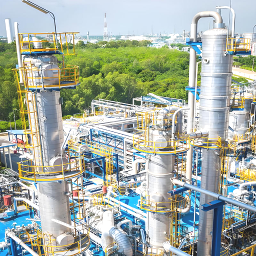
1. What does FCC mean in a refinery?
FCC is the abbreviation of Fluid Catalytic Cracking. In a refinery, it is the process, followed on by the equipment (referred as “cat cracker”), which utilizes a fluidized zeolite catalyst to break down the heavy gas oil (vacuum gas oil / VGO) into more volatile distillates. FCC is the dominant process for the production of gasoline in most of the present day oil refineries around the globe.
2. How much does fluid catalytic cracking cost?
A worldscale FCC unit (75-120 kbd) has an installed capital cost of the order of US$300 million to over US$1 billion, depending on plant capacity, whether unit is designed to process conventional vacuum gas oil or a heavier atmospheric residue (RFCC), location, and level of environmental compliance necessary. These are order-of-magnitude estimates based on recently observed market data (2025-2026); current engineering and construction market prices vary significantly by region and contracting strategy. Operating costs are mainly associated with catalyst makeup, utilities (air blower, steam), and maintenance turnarounds (every 2-3 years).
3. What is the difference between fluid catalytic cracking and hydrocracking?
Cracking with a zeolite acid catalyst at ca 535 °C removing carbon (deposited on to catalyst as coke, then burned off). No hydrogen is present and operates at a low pressure of ca 1.7 bar. Heavy gas oil produced other than lighter gas oils, mainly as high-octane gasoline.
Hydrocracking involves the use of hydrogen (high pressure up to 250 bar, injected at the catalyst bed) and over bifunctional catalyst to produce high specification, low-sulfur diesel and kerosene from similar feeds (see ULSD specification). FCC is cheaper and best suited to making gasoline. High pressure hydrocracking costs are greater but maximises middle distillate quality and provides a more efficient process for treating feeds with higher aromatics, aromatic or high-sulfur constituents.
4. Who invented fluid catalytic cracking?
Developed by Donald Campbell Homer Martin Eger Murphree and Charles Tyson at Standard Oil of New Jersey (ExxonMobil)US Patent 2,451,804, FCC Pack was first patented by them although the friutalized-catalyst principle was discovered by Warren K. Lewis and Edwin R. Gilliland at MIT.
The first commercial FCC was put on-stream in 1942 at Standard Oil’s Baton Rouge refinery-about 13000 bbl/day.
5. What is vacuum gas oil (VGO) in FCC?
Vacuum Gas Oil (VGO) is currently used as typical FCC feed-stock – the heavy distillate fraction (generally separated in the vacuum distillation tower and boiling from ca.340-565 C) of crude oil. The VGO is excluded further use in direct diesel or petrol fuel due to its heavy high boiling nature. It still contains the lighter end of the refineries distillation cut that are cracked in the FCC riser to produce petrol and LPG.
RFCC plants which are generally heavier than VGO feed material will also process Atmospheric Residue or Vacuum Residue feed-stocks both of which have higher CCR and metals concentrations than conventional VGO feedstocks.
6. What are the main environmental concerns with FCC units?
Regenerator flue gas from the FCC is the dominant source of emissions. It carries SOx (from the coke sulfur), NOx, carbon monoxide, and catalyst fines in the form of particulate. Equipment on modern units includes: electrostatic precipitators or cyclone primary fines removal (recovering 70-90% of the catalyst fines), CO combustion promoters or a CO boiler, and a wet gas scrubber to remove the SOx.
The carbon dioxide produced from the coke combustion in the FCC regenerator is an emerging issue in the EPA, EU and ICAO emissions control regulations, and retrofit schemes for capturing and re-using (CCU) the CO are under review for existing units.
Planning an FCC Turnaround or Maintenance Scope?
Boshiya manufactures and supplies special equipment for oil refinery turnaround: heat exchanger bundle pullers, tube bundle cleaning devices, self-propelled extractors for preheaters of FCC feed, for product coolers and main column overhead condensers. The equipment is adapted to the fouling state typical of FCC service.
References & Sources
- U. S. Energy Information Administration (EIA). “U.S. Refinery Capacity Report – Operable Atmospheric Crude Oil Distillation Capacity, 2024.” eia.gov/dnav/pet/pet_pnp_cap1_dcu_nus_a.htm
- Oloruntoba, A., Zhang, Y., and Hsu, C.S. “State-of-the Art Review of Fluid Catalytic Cracking (FCC) Catalyst Regeneration Intensification Technologies”. Energies (MDPI), 15(6), 2061, 2022. DOI: 10.3390/en15062061
- Vogt, E.T.C. & Weckhuysen, B.M. Fluid catalytic cracking: recent developments on the grand old lady of zeolite catalysis.Chemical Society Reviews 44 7342-7370.2015. RSC Publishing.
- U.S. Department of Energy / Bioenergy Technologies Office (BETO). Co-Processing of Fast Pyrolysis Bio-Oils and Hydrothermal Liquefaction Bio-Crudes in Fluid Catalytic Crackers. energy.gov/cmei.Webinar: 20 September 2023; page last reviewed 2025.
- Federal Reserve Bank of Dallas. “Dallas Fed Energy Indicators – October 2024”. dallasfed.org/research/energy/indicators/2024/en2410
- Research and Markets / GlobeNewswire. “Fluid Catalytic Cracking Market Research Report 2026 – Global Industry Size, Share, Trends, Opportunity and Forecast, 2021-2031”.01/22/2026.
- Wikipedia contributors. “Fluid catalytic cracking.” Wikipedia. Accessed 2026 April. [Yields from Sadeghbeigi, R., Fluid Catalytic Cracking Handbook, 2 ed., Gulf Publishing, 2000. ]
- AFPM. “U.S. Refinery Capacity Report 2024.” American Fuel & Petrochemical Manufactures 2024.
![Polypropylene Resin: Grades, Types & Selection Guide [2026]](https://boshiya.com/wp-content/uploads/2026/05/0-150x150.webp)