Get in Touch with BOSHIYA

Heat Exchanger Approach Temperature: Definition, Calculation and Performance

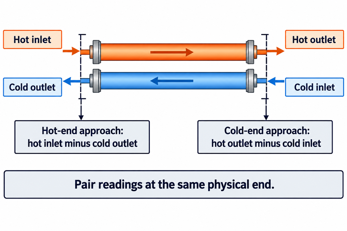
Heat exchanger approach temperature is the temperature difference between two specified fluid temperatures. For a steady, single-phase counterflow exchanger with approximately constant fluid properties and negligible heat loss, the minimum approach is the smaller of its two terminal gaps: hot inlet minus cold outlet, and hot outlet minus cold inlet. Always identify the temperature pair before using the number.
Contents
show
In a hypothetical counterflow example, a hot stream cools from 100°C to 60°C while a cold stream warms from 30°C to 80°C. Its cold outlet exceeds its hot outlet, yet heat moves from the hotter fluid to the colder fluid at each end. The physical positions explain the process.
Heat Exchanger Approach Temperature: What the Number Means
An approach describes how close a stream comes to a reference temperature, and a small approach temperature means little driving temperature difference at that location. Heat duty, the rate of heat transfer, also depends on the fluids, flow rates and exchanger conductance.
According to Alfa Laval, heat load can be calculated using the flow rate, specific heat and temperature difference on one side.
What is the approach temperature in a heat exchanger?
In a simple counterflow heat exchanger, calculate the temperature difference at the hot inlet and cold outlet and at the hot outlet and cold inlet, and state the smaller value when specifying the minimum approach. Label a single reported terminal temperature difference value by its location for another engineer to reproduce it.
The hot and cold fluids enter opposite ends. This flow arrangement, described in MIT’s heat-exchanger analysis, places each stream adjacent to fluid at a different temperature. This local temperature difference acts along the heat transfer surface. Subtracting both outlet temperatures compares readings from opposite ends.
- Hot-end approach: Th,in − Tc,out.
- Cold-end approach: Th,out − Tc,in.
- Minimum terminal approach: The minimum temperature difference at terminals for this arrangement.
The exchangers work through separating walls and are used to transfer heat between two fluids. Each fluid goes through its own temperature change: the cold stream absorbs the heat from the hot stream and warms up. Those stream changes address a different question from the temperature approach between streams.
Approach Temperature Calculation from Four Temperatures
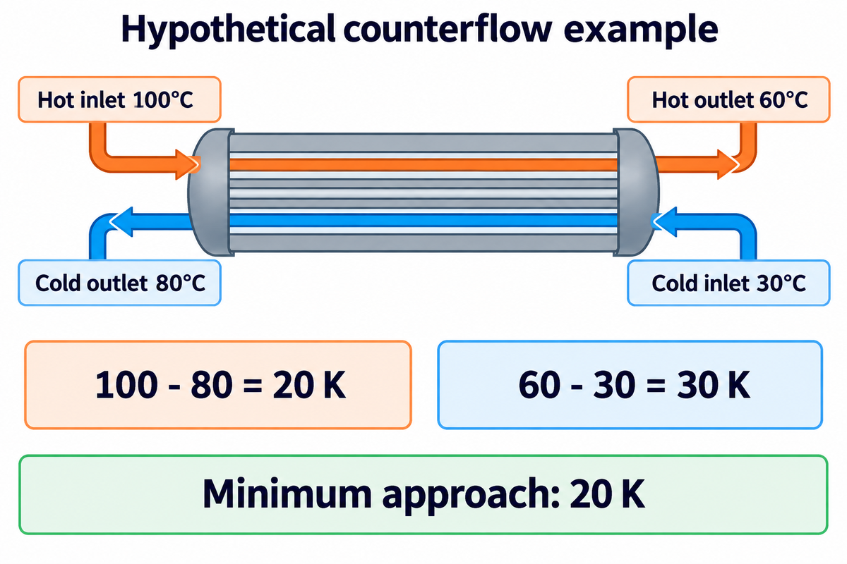
For the assumed 100→60°C hot stream and 30→80°C cold stream, the terminal gaps are 20 K and 30 K, giving a minimum approach of 20 K. Calculate these gaps using all four temperature readings, pairing the hot and cold readings at each physical end according to the flow directions.
Four-Temperature Pairing Test
Use this worksheet to make an estimate of temperature approach auditable. The example considers a steady, single-phase counter-flow heat exchanger with approximately constant fluid properties and negligible heat loss; more complex flow arrangements or phase changes require an appropriate temperature profile. This worksheet is based on MIT’s counterflow heat balance.
| Record or check | Example | Meaning |
|---|---|---|
| Hot inlet, Th,in | 100°C | Hot stream enters at hot end |
| Hot outlet, Th,out | 60°C | Hot stream leaves at cold end |
| Cold inlet, Tc,in | 30°C | Cold stream enters at cold end |
| Cold outlet, Tc,out | 80°C | Cold stream leaves at hot end |
| Hot-end pair | 100 − 80 = 20 K | Local terminal driving difference |
| Cold-end pair | 60 − 30 = 30 K | Other local terminal difference |
| Minimum terminal gap | min(20, 30) = 20 K | Limiting end in this example |
| Hot-stream range | 100 − 60 = 40 K | Temperature fall of one stream |
| Cold-stream range | 80 − 30 = 50 K | Temperature rise of one stream |
| Outlet comparison | 80 − 60 = 20 K | Temperature cross; different physical ends |
To examine sensible heating and cooling, calculate Q = ṁcpΔT on each side, and compare the duties to determine heat balance. Here ṁ is mass flow rate and cp is specific heat. At an assumed heat transfer rate of 100 kW, the hot side heat capacity rate is 2.5 kW/K and the cold side rate is 2.0 kW/K; both sides give the same duty.
A smaller heat capacity rate gives a larger stream temperature change at the same duty. A large difference between the calculated duties calls for checking flow measurements, fluid properties, and heat loss. Correct arithmetic can’t correct temperatures logged at different loads or a hot fluid outlet temperature assigned to the wrong nozzle.
Approach Temperature vs LMTD, Range and Temperature Cross
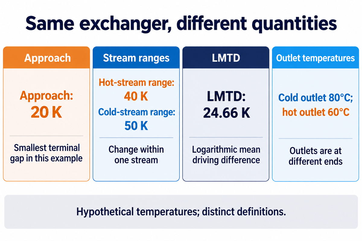
Approach is a defined temperature gap; range is the change in a single stream from inlet to outlet; LMTD is the logarithmic mean driving difference used in thermal calculation. Temperature cross compares the two outlet temperatures. These quantities may have different values on the same exchanger because they compare different points or summarize different behavior.
| Term | Calculation basis | Useful question |
|---|---|---|
| Approach | Specified terminal or equipment-specific pair | How close are these temperatures? |
| Range | Inlet minus outlet, or outlet minus inlet, on one stream | How much did this stream change? |
| LMTD | Logarithmic mean of the terminal driving differences | What driving difference enters the duty calculation? |
| Temperature cross | Cold outlet compared with hot outlet | Does the cold stream leave hotter than the hot stream? |
For positive terminal differences ΔT1 and ΔT2, the log mean temperature difference is:
LMTD = (ΔT1 − ΔT2) / ln(ΔT1 / ΔT2)
The worksheet’s terminal differences give an LMTD of 24.66 K. It’s between the terminal values, but differs from their arithmetic mean, or average temperature difference. The MIT derivation relates this driving difference to heat transfer area and overall heat transfer coefficient.
When both terminal differences are the same, LMTD = that common difference. For an assumed hot stream of 90→50°C and a cold stream of 20→60°C, both terminal differences are 30 K, and the LMTD is also 30 K. The equal-terminal LMTD limit should be used in place of evaluating a zero divided by zero expression.
Physical temperature cross in counterflow is possible, as the two outlets are at different ends. Heat energy is transferred locally from higher temperature to lower temperature. An impossible local cross within the heat exchanger is a different situation, and checking the flow arrangement and temperature profiles will resolve this.
Multipass or crossflow heat exchanger equipment may require an LMTD correction factor, F, or a more detailed rating method. A terminal-only heat exchanger analysis must account for that arrangement before predicting capacity.
Approach Temperature by Application: Definitions and Examples
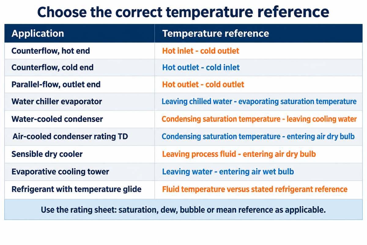
The temperature pair used depends on the application. For example, an air-cooled condenser uses saturated condensing temperature and entering air dry-bulb temperature, while a cooling tower uses leaving water and entering air wet-bulb temperature. Determine the definition before comparing a given reading with a specification, other exchangers or a supplier’s claim.
| Application or location | Temperature pair | Check on the rating sheet |
|---|---|---|
| Counterflow, hot end | Hot inlet − cold outlet | Both readings belong to hot end |
| Counterflow, cold end | Hot outlet − cold inlet | Compare with hot-end gap |
| Parallel-flow, outlet end | Hot outlet − cold outlet | Both streams leave at same end |
| Water chiller evaporator | Leaving chilled water − specified evaporating saturation temperature | Refrigerant pressure location and reference |
| Water-cooled condenser | Specified condensing saturation temperature − leaving cooling water | Use the equipment’s stated definition |
| Air-cooled condenser rating TD | Specified saturated condensing temperature − entering air dry bulb | Rating TD differs from a water-side outlet approach |
| Sensible air-cooled heat exchanger (dry cooler) | Leaving process fluid − entering air dry bulb | Entering-air condition and recirculation |
| Evaporative cooling tower | Leaving water − entering air wet bulb | Wet bulb, not dry bulb |
| Refrigerant with temperature glide | Specified fluid temperature versus the stated refrigerant reference | Dew, bubble or mean reference, as applicable |
ASHRAE’s cooling-tower chapter shows the meaning of approach is different than the meaning of range. With a given heat load and flow of water, a tower’s capability is defined by the temperature level at which the load is rejected. ASHRAE’s chapter on condensers defines the term air-cooled rating temperature difference using entering air and saturated condensing conditions.
Other distinctions include refrigerant blends. At a given pressure, a zeotropic mixture changes temperature during a phase transition; this change is called temperature glide. ASHRAE’s temperature glide guidance defines mean temperature, bubble point and dew point temperatures. The refrigerant and rating convention should be included with the reported approach.
What is a good approach temperature for a heat exchanger?
The “best” approach for different heat exchanger types depends on the design and construction constraints, cost and given heat-load requirement of the process. Compare ratings for heat exchangers using the application’s specified temperature pair at the same flow rates, fouling basis, and allowable pressure drop.
A closer approach in waste heat recovery may help recover heat that would otherwise leave the process. For a cooling service, a warmer seasonal utility supply can make the outlet requirement harder to achieve. Jensen and Skogestad’s study on minimum approach specifications shows early fixation of an approach can constrain an economic design. The authors’ critique of an approach constraint does not invalidate network pinch for a process with fixed stream data.
Close Approach Heat Exchangers: Area, Cost and Heat Recovery
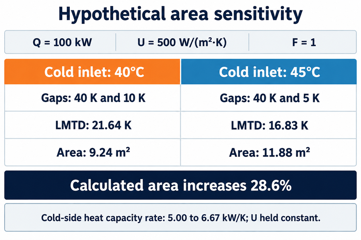
A closer approach usually reduces the thermal driving difference for a specified heat transfer duty and may therefore increase surface area.
Area sensitivity with stated assumptions
Consider two hypothetical counterflow designs with Q = 100 kW, U = 500 W/(m²·K) and F = 1. Hold the hot stream at 100→50°C and the cold outlet at 60°C; change the cold inlet from 40°C to 45°C. The thermal sizing relation gives A = Q / (UF × LMTD).
| Cold inlet | Terminal gaps | LMTD | Required area |
|---|---|---|---|
| 40°C | 40 K and 10 K | 21.64 K | 9.24 m² |
| 45°C | 40 K and 5 K | 16.83 K | 11.88 m² |
Halving the minimum approach increases the calculated area by 28.6% in this example. The cold-side heat capacity rate must change from 5.00 to 6.67 kW/K to preserve the duty. It’s assumed here that U remains constant. Changing flow in an exchanger also changes convection and pressure loss.
More area is needed for the same duty and LMTD at a lower heat transfer coefficient. A large heat exchanger also needs space and support. IPIECA’s cost guidance includes pipe work, controls, pumps, foundations and commissioning in the scope of an installed system. An area ratio alone can’t price that package.
Heat-recovery payback example
In this separate hypothetical investment, a closer approach adds an assumed 25 kW of useful heat recovery for 6,000 hours per year. Assume the displaced energy is worth $0.08/kWh, added annual costs are $2,000, and incremental installed cost is $30,000. UMD defines net savings as the value of energy generated less operation and maintenance expenses. UMD calculates simple payback by dividing the total system cost by annual net savings.
- Useful recovered energy: 25 × 6,000 = 150,000 kWh/year.
- Gross annual value: 150,000 × $0.08 = $12,000/year.
- Net annual saving: $12,000 − $2,000 = $10,000/year.
- Simple payback: $30,000 / $10,000 = 3 years.
This uses the definition of simple payback from the University of Maryland Extension. Waste heat has value only when a useful load absorbs heat at the available temperature and time; using heat for an intermittent load changes the annual recovery.
Increased heat recovery can justify additional equipment when the recovered energy displaces a purchased utility. To maximize heat recovery economically, evaluate the recovered energy value against pumping, cleaning and capital costs. The maximum possible heat transfer is a thermodynamic limit, not automatically the best investment.
Plate vs Shell-and-Tube for Close Temperature Approaches
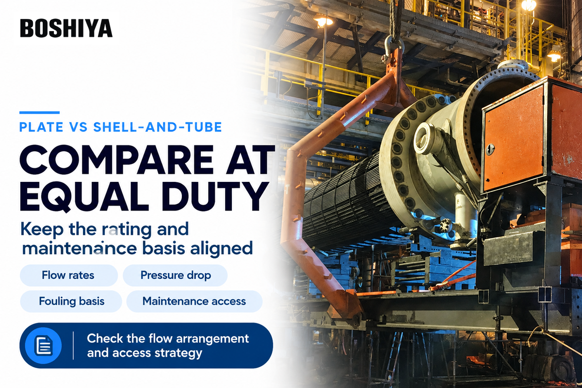
Plate heat exchangers can provide compact counterflow with high heat transfer, while a shell and tube heat exchanger can offer different mechanical layouts and access options. Choose the type of heat exchanger based on the required fluid pair and operating cases. Sometimes, the best choice between competing designs comes down to pressure loss and maintainability.
Plate arrangements
- A gasketed plate and frame heat exchanger can be opened for plate inspection; reserve the required opening space.
- Brazed plate heat exchangers have a different service-access strategy because the plate pack is permanently joined.
- Confirm passage suitability for solids, pressure loss and the fluid’s viscosity at operating temperature.
Tubular arrangements
- A tube heat exchanger may use multiple passes; thermal rating must reflect the resulting flow pattern.
- Removable bundles need extraction clearance, handling access and appropriate support.
- Tube-side and shell-side cleaning access differ with construction.
IPIECA’s equipment comparison categorizes construction, fouling, and maintenance as selection factors. Compare the shell and tube exchanger to the plate heat exchanger at the same duty and allowable pressure drop and consider the same allowance for deposit buildup.
Alfa Laval provides gasketed plate-and-frame equipment for close-temperature-approach duties. Xchanger offers a range of fin-tube and fin-plate heat exchangers for industrial temperature control. These gas-cooling designs have different rating bases.
Heat exchanger design begins with a characterization of the fluid properties and required operating envelope. When selecting a heat exchanger, separate material compatibility from thermal approach. For selecting stainless steel shell-and-tube heat exchangers and arrangements, see our guides on stainless steel shell-and-tube heat exchangers and shell-and-tube exchanger arrangements.
Heat exchanger selection includes the surrounding process and its role in heat exchanger networks, even when buying only one unit. For example, changing one outlet temperature changes the energy available for heat recovery in another service. A practical heat exchanger must meet that duty throughout the specified operating temperature range and remain accessible for its planned maintenance.
Interpreting a High or Changing Approach Temperature
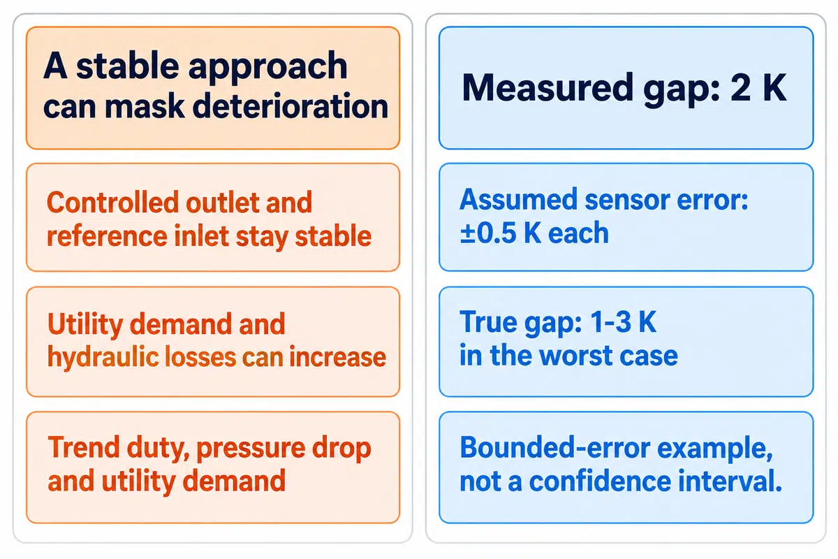
Fouling, altered load, utility temperature, flow distribution, or measurement error can change the approach. Fouling can reduce heat transfer, while a changed utility inlet changes the available driving difference. Compare the reading with the reference operating conditions; an approach may appear stable while exchanger performance deteriorates if a controller compensates.
Patil and colleagues’ study of heat exchangers under temperature control shows why duty-only monitoring can miss fouling when additional utility flow preserves the controlled temperature. Demand and hydraulic losses increase if utility flow is high, and the controlled temperature is stable. If the controlled outlet and reference inlet remain stable, their approach can remain stable while utility demand and hydraulic losses increase.
Compare on a common basis
- Check load, both flow rates and utility inlet temperature.
- Trend duty and pressure drop alongside the approach.
- Record controller demand or utility consumption where relevant.
- Check sensor placement, calibration and sampling time.
Avoid mismatched comparisons
- Do not compare different seasonal or production loads as equivalent tests.
- Do not compare temperature gaps calculated from different sensor pairs.
Suppose the measured temperature difference between the hot and cold streams at one end is 2 K, and each sensor has an assumed bounded error of ±0.5 K. It could be that the difference in temperature is actually 1 to 3 K in the worst case scenario. The true gap could be 1–3 K under the worst combination of errors; this is an error-bound illustration, not a statistical confidence interval.
NIST’s guidance on quantifying combined uncertainty states that individual input uncertainties and their covariance should be considered while calculating combined standard uncertainty. The assessment should include how the sensors were placed, calibration, and the time of sampling, especially when the approach is small.
Undersized heat exchangers and units affected by deposits can both miss an outlet target, but they require different responses. Use the separate heat exchanger fouling assessment to analyze deposits, and use the heat exchanger bundle cleaning guide for response options.
Specifying and Verifying a Temperature Approach
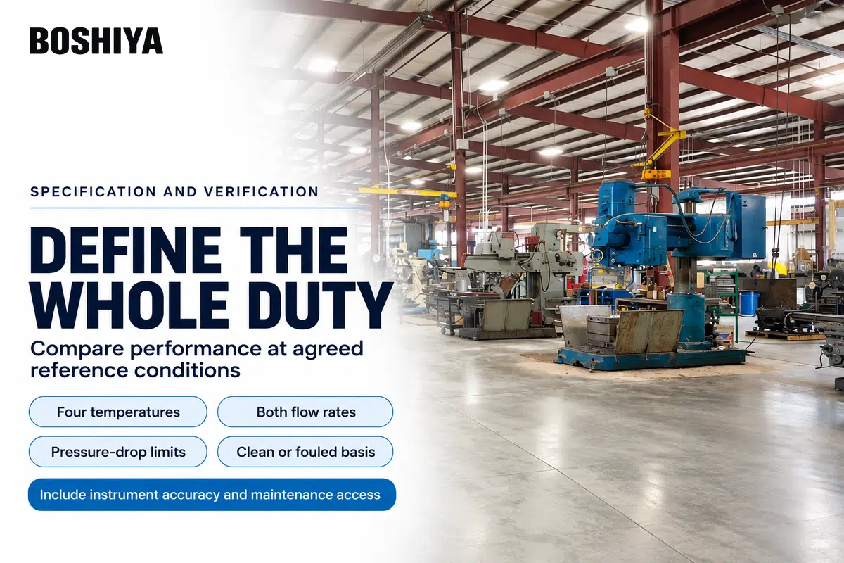
State the complete thermal duty, as well as the approach definition, in the request. The supplier must have the various fluid streams and properties, four temperature targets, both flow rates, allowable pressure drops, and design basis (i.e. clean or fouled). Acceptance should compare the tested exchanger’s performance with the agreed reference case, accounting for measurement uncertainty.
“This Code provides methods and procedures for testing single phase heat exchangers.”
ASME PTC 12.5 addresses heat transfer rate, overall heat transfer coefficient and pressure drop, with performance projected to reference conditions. Its single-phase scope is relevant when choosing an acceptance method; condensing or evaporating duties need their applicable test basis.
- Process basis: fluid composition, phase and properties, plus how the heat exchangers operate at normal and limiting conditions.
- Thermal basis: Temperature locations, heat duty, and flow rates with fouling allowance.
- Hydraulic basis: allowable pressure drop on each side and expected utility demand.
- Test basis: stable conditions, instrument accuracy, reference-condition corrections and acceptance tolerances.
- Maintenance basis: cleaning method, isolation provisions and mechanical access.
Fouling assumptions affect the design of heat exchange equipment, including shell and tube arrangements. In their discussion of specification mistakes, Musa Smakaj and Professor Mads Kyed write, “A single default number rarely fits.” Make the intended run and cleaning basis explicit to allow competing designs to incorporate comparable assumptions.
The 10/13 rule refers to pressure design and tube-rupture assessment. The Society of Petroleum Engineers’ heat-exchanger equipment overview discusses it under shell-side design pressure; a thermal approach is a temperature difference between the specified locations.
For removable tubular bundles, review tube sheet design and access together with extraction space. BOSHIYA’s heat exchanger bundle pullers address tube bundle handling during equipment maintenance. The thermal rating of the exchanger remains part of the process design.
Frequently Asked Questions
What will be the outlet temperature of water?
For single-phase water, outlet temperature equals inlet temperature plus Q/(ṁcp) for heating, or minus Q/(ṁcp) for cooling.
This assumes approximately constant specific heat, with Q as heat duty and ṁ as mass flow rate. If the duty is unknown, an exchanger rating is also needed. Approach alone leaves the fluid flow and available heat unspecified, so it can’t determine the water outlet.
Where is approach temperature measured?
In simple counterflow, calculate an approach from the hot inlet and cold outlet, or the hot outlet and cold inlet, at the same physical end.
Record all four temperatures and the sensor locations. Chillers and cooling towers use different reference temperatures, so keep the equipment definition with the result to allow comparison with the same rating.
What causes heat exchanger performance to drop?
Fouling, changed flow, different inlet conditions and measurement problems can all affect apparent performance.
Deposits add thermal resistance and may restrict passages, while changed utility conditions alter the available driving difference. Compare duty, temperatures and pressure drop at the same load and flow conditions. This separates a changed operating case from a change in the exchanger’s thermal behavior.
Does a temperature difference of 1°C equal 1 K?
Yes. A temperature difference of 1°C equals 1 K, and either corresponds to a difference of 1.8°F.
Celsius and kelvin have equally sized increments but different zero points. Keep absolute temperature conversions separate from temperature-difference conversions when entering values into an approach or LMTD calculation.
Can the approach reach zero in a real exchanger?
Exactly zero isn’t a practical finite-area target for the usual sensible counterflow problem at nonzero duty.
The limiting terminal gap is approached as conductance increases. Equal outlet temperatures are different: counterflow outlets occupy different ends, so their equality doesn’t establish a zero local driving difference. A near-zero instrument reading also needs to be assessed against measurement uncertainty and the actual flow arrangement.
What is the difference between a condenser and a heat exchanger?
A condenser is a heat exchanger that removes heat while a vapor becomes liquid.
Heat exchangers are used for both sensible and phase-change duties. Condensation introduces a saturation-temperature reference, whereas a sensible exchanger heats or cools streams without changing phase. Condenser ratings can also include desuperheating and subcooling, so use the specified temperature pair and refrigerant reference when interpreting its approach.
References & Sources
- MIT: Heat Exchangers, Thermodynamics and Propulsion, §18.5.
- IPIECA: Heat exchangers, Energy Efficiency Compendium.
- Jensen and Skogestad: Problems with specifying minimum approach temperature in process design.
- ASHRAE Handbook: Cooling Towers; Condensers; Temperature Glide.
- Patil et al.: Monitoring fouling in heat exchangers under temperature control based on excess thermal and hydraulic loads, Chemical Engineering Research and Design, 2022.
- NIST Technical Note 1297: Law of Propagation of Uncertainty.
- ASME PTC 12.5: Single Phase Heat Exchangers.
- University of Maryland Extension: Energy 101, Simple Payback.
- Smakaj and Kyed: Seven Specification Mistakes in Heat Exchanger Projects, Heat Exchanger World.
- Society of Petroleum Engineers: Static Equipment, Understanding Heat Exchangers, 2019.
About the publisher: BOSHIYA supplies heat exchanger bundle handling equipment. This guide explains some basic thermal concepts and calculations to bridge the language gap during specification and maintenance of heat exchangers.