Get in Touch with BOSHIYA


A tube sheet heat exchanger holds tube ends with a perforated plate and helps separate the two fluid circuits. For maintenance personnel, the first question is, what’s the location of the fault: tube wall, tube joint, the plate or a gasket? Each case warrants a different repair.
Contents
show
Updated October 2026
A tube sheet heat exchanger has tubes secured in a drilled plate. The plate supports the ends and separates shell-side and tube-side spaces. Double tubesheets add an intermediate leak space; tube-wall damage remains a separate failure path.
Key points
- Double tubesheets expose certain joint leaks; they don’t stop fluid passing through a damaged tube wall.
- A seal weld and a strength weld perform different jobs.
- Normal bulk material properties can coexist with serious local weld defects.
- Plugging a leaking tube changes the available flow area and heat-transfer surface.
- The TEMA 2026 edition includes a transition period for work already in process.
Quick Specs
| Component | Tube-end support and part of the fluid-separation boundary |
|---|---|
| Construction choices | Single or double sheets; fixed, floating or U-tube arrangements |
| Joint methods | Mechanical expansion, welding, or a specified combination |
| Design considerations | Both-side pressure and temperature, material, hole pattern and thermal movement |
| Maintenance starting point | Locate the leak path before selecting the repair |
What Is a Tube Sheet in a Heat Exchanger?
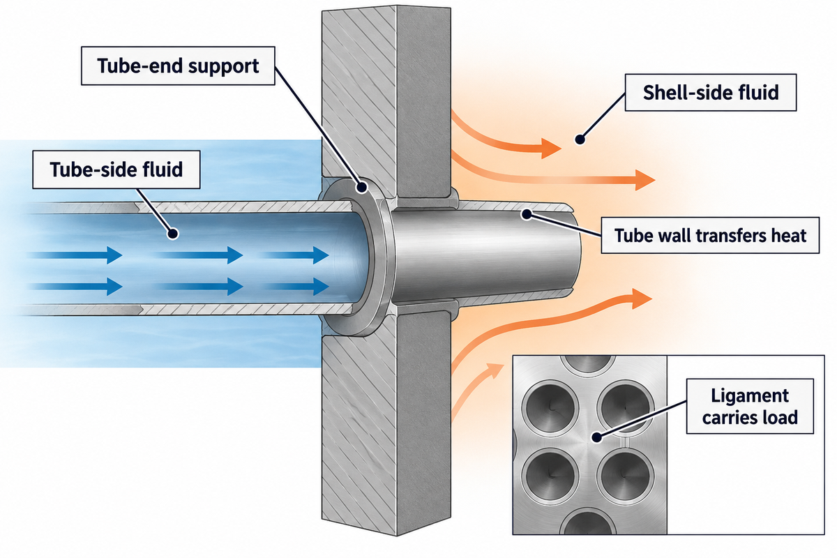
A tube sheet is a plate into which the ends of the tubes are secured. In a shell and tube heat exchanger, its joints separate the fluid inside the tubes from the fluid outside them. The plate also transfers loads between tubes and the surrounding exchanger structure.
Think of a thick board with holes drilled through it, but the openings must hold pressure bearing connections. A tubesheet is often a round flat piece of metal, but its engineering function goes well beyond positioning the tubes. The metal between adjacent holes, called a ligament, must also bear the load.
The tube side fluid enters a channel or bonnet, flows through the tubes and leaves through the outlet. A second fluid flows in the shell, around the outside of the tubes. Heat passes primarily through the tube walls from the hotter fluid to the cooler fluid.
Channels and shell enclose separate spaces. Inlet and outlet pipe connections carry fluid to and from the unit. At the end of the heat exchanger, a flange and a gasket may form a pressure boundary. A partition in the channel may direct flow through multiple passes; leakage across that partition may affect thermal performance.
The FDA’s technical guide on heat exchanger contamination describes tube ends secured into plates and identifies those joints as possible leakage points. Its anatomy is useful even though the guide dates from 1979.
To understand the complete flow and heat-transfer arrangement, consult our shell and tube heat exchanger guide. A plate heat exchanger uses a different core construction and doesn’t employ this drilled tube end assembly.
Single vs Double Tube Sheet: What Changes?
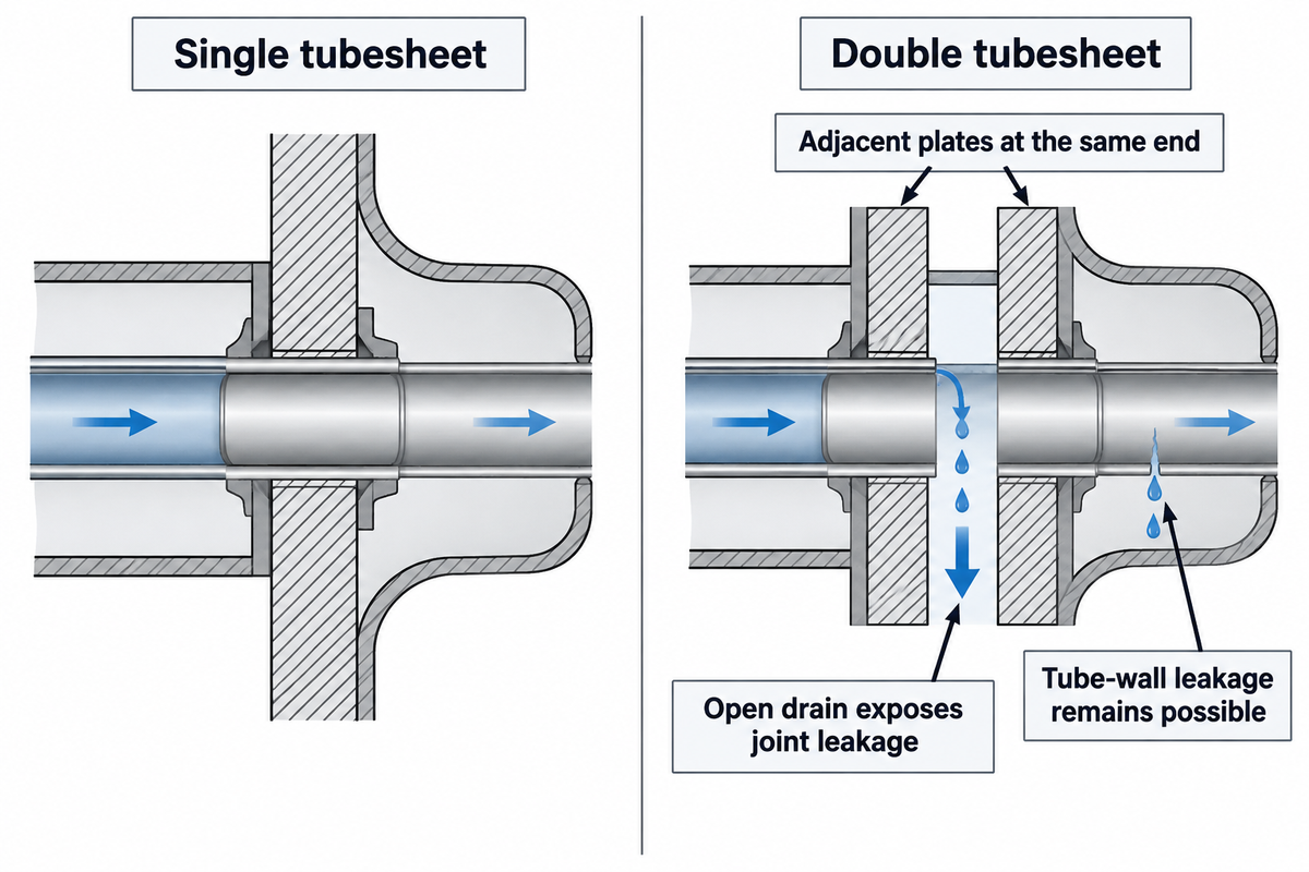
A double tube sheet arrangement adds a second joint boundary and an intermediate space at one end of the exchanger. In an open, drained design, a leaking joint can discharge into that space instead of directly into the other fluid circuit. Protection is provided by an open drain.
Single tubesheet
- One sheet at a given end separates the channel and shell spaces.
- Tube joints sit at the shared boundary.
- Joint leakage can connect the two circuits.
Double tubesheet
- Two adjacent sheets create an intermediate space.
- Each tube passes through both joint boundaries.
- An open drain exposes leakage from either boundary.
The inner tube sheet faces the shell-side space. The outer tube sheet faces the channel. These are adjacent plates at the same end, not the two plates at the opposite ends of a straight-tube exchanger.
“it is important that the drain ports be open and free to discharge any leakage that may occur”
U.S. Food and Drug Administration, Inspection Technical Guide 34, 1979
A plugged drain or an inaccessible leakage space defeats the observation path. The design also requires a suitable destination for discharged fluid. Otherwise, a visible leak still can create a chemical or temperature hazard.
Consider a process exchanger with clean product in the tubes and a heating utility in the shell. The concern is leakage through a tube end joint. An open double-sheet arrangement gives that leak an external route and a location to observe it. During a shutdown, paint, deposits or an added cover could obstruct that route. The maintenance scope therefore includes the interspace and its discharge path, not just the tube joints. If the failure is a perforation farther along the tube, the leak passes through the tube wall. An extra sheet at the end doesn’t block that leak.
Fixed, Floating and U-Tube Tubesheet Arrangements
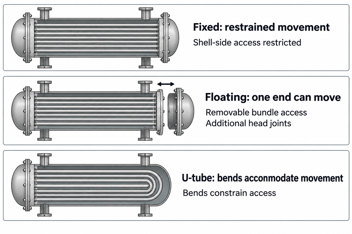
Fixed, floating and U-tube arrangements determine how the tube assembly moves relative to the shell. A fixed tube sheet restrains that movement; a floating head allows one end to move; U-tubes accommodate movement through their bends. These affect the thermal stress as well as maintenance access separately from single- versus double-sheet construction.
| Arrangement | Movement | Maintenance implication |
|---|---|---|
| Fixed tubesheets | Both ends are attached to the shell construction. | Tube bores may be accessible after opening the channels; shell-side mechanical access is restricted. |
| Floating head | One end moves relative to the shell. | Removable construction permits bundle access, with additional head joints to inspect. |
| U-tube | Both ends return to one sheet; bends accommodate movement. | The bundle may be removable, while bends and inner rows constrain tube cleaning and replacement. |
These are construction principles, not instructions to pull every bundle. A sheet welded into a fixed assembly does not become removable because a lifting attachment is available. The shell openings, flange dimensions and the actual fabrication drawing determine access.
Long tube lengths and different temperatures of the metals of the shell and tubes can cause different expansion of the two assemblies. That’s one of the reasons heat exchanger design must consider the complete assembly, including an expansion joint where the design so requires.
Our U-tube heat exchanger article provides additional information about bend access and removal. Once a removable tube bundle and the handling scope are established, the BOSHIYA bundle puller range covers extraction equipment.
Tube Sheet Materials and Corrosion Compatibility
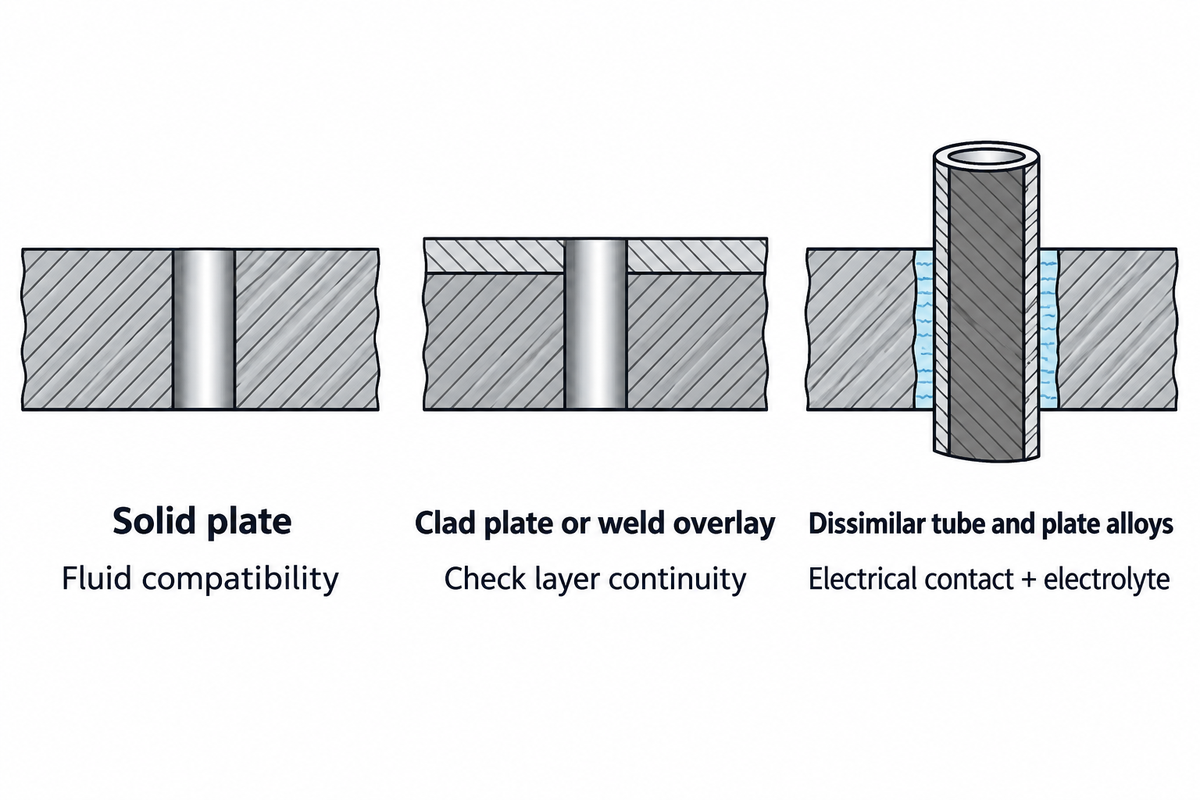
Tube sheet materials must be adapted to the process fluids and the joining method. Low carbon steel can serve as a structural base, while stainless steel or other corrosion-resistant alloys can be used to protect surfaces. In constructions, a clad plate can perform these functions, but damage through the protective layer can expose a different material.
The actual fluid composition and temperature, including shutdown and cleaning conditions and the chemicals used, determine the material of choice. Cooling water can create a different local environment under a deposit or in a joint crevice than in a freely flowing stream.
| Construction | Useful distinction | Condition to examine |
|---|---|---|
| Solid plate | The plate has one bulk material grade. | Fluid compatibility, corrosion allowance and joint qualification |
| Clad plate or weld overlay | A corrosion-resistant surface covers a structural base. | Layer continuity at holes, welds and repaired areas |
| Dissimilar tube and plate alloys | The joint combines different mechanical and electrochemical behavior. | Thermal expansion mismatch, weldability and galvanic exposure |
The Euro Inox guide to stainless steel in contact with other metals provides the conditions for galvanic corrosion. For corrosion to occur, the two metals have to be connected electrically and an electrolyte has to be present. Wetted surface area and the environment affect the outcome; a potential difference doesn’t indicate the rate of corrosion.
It isn’t sufficient to match names only. For example, a stainless steel tube and a stainless steel plate may differ in grade, heat treatment, or response to welding. Duplex assemblies require attention to heat input and shielding during welding. Joint Procedure Qualification focuses on the combination, rather than the tube material in isolation.
The historical Surry Unit 2 example shows why repair history needs to be included in material review. In 1991, a tube plug was removed by drilling, which left an off-center damaged tube end. In 2006, inspectors found yellow staining attributed to corrosion of the tubesheet material. The operator evaluated the damage and installed a special plug. NRC Information Notice 2013-20 provides details regarding the damage and site-specific assessment. Use the case as a reason to check repair history, not as a defect-size limit for other exchangers. For a clad assembly, the corresponding question is whether previous drilling, grinding, or weld repairs have exposed the base metal.
Tube-to-Tubesheet Joints: Expanded, Welded or Both
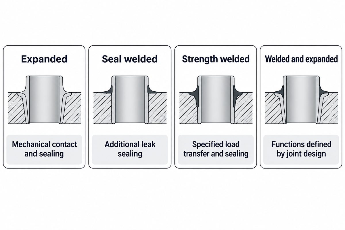
Tube expansion changes the tube geometry to press it into contact with the hole wall. Joints which are fusion welded join the tube end with the plate metal. For a fusion weld, the tube is fused to the base material. A seal weld primarily provides a leakage seal, while a strength weld is designed to carry the specified joint load. Combined construction assigns a defined role to each operation. A fusion weld produces a metallurgical bond between the tube and plate.
| Joint | Primary function | Fabrication concern |
|---|---|---|
| Expanded | Mechanical contact and sealing at the tube hole | Measured fit, controlled wall reduction and expansion length |
| Seal welded | Additional leak sealing | Do not assign an unspecified structural load to the weld |
| Strength welded | Specified load transfer and sealing | Qualified joint geometry, welding procedure and examination |
| Welded and expanded | Functions defined by the joint design | Sequence and expansion depth must avoid damaging the weld |
Elliott Tool’s guidance on expanding welded tube joints describes the difference between strength welding and seal welding. A strength weld provides the mechanical joint; additional expansion can address a separate design objective, such as reducing the annular crevice.
What is tube expansion in a heat exchanger?
Plastic expansion of a tube within its tubesheet hole by tube rolling forms a tight fit. Either roller tooling or hydraulic expansion can perform this operation. Control is based on the joint procedure and the geometry of the tube and tubesheet clearance. The tube rolling process takes up clearance and reduces the wall thickness, which changes the final bore.
In Elliott’s wall-reduction method, the tube outside diameter, wall thickness and tube hole are measured before the tube rolling process. Tube diameters alone don’t indicate the clearance.
Over-expansion can thin the tube end and distort adjacent ligaments. Further rolling is therefore not the default response to a leaking joint. Determining the cause of a leaking new joint and a damaged, thinned joint requires different assessments.
Welding a damaged steel tube end adds another constraint: the remaining material and plate alloy must support the proposed weld procedure. Welding an unsuitable joint can’t restore lost metal. Examination access and acceptance criteria of the fabrication process belong in the construction plan, prior to completing the joint.
Tube Sheet Design: Thickness, Holes and Thermal Loads
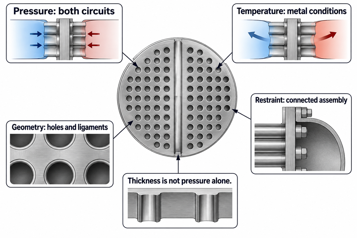
Tube sheet design accounts for pressure loading, perforated-plate strength and tube and shell forces. Thickness can’t be assessed from pressure loading alone. Hole patterns, material and joint properties, thermal expansion and other features of the connected parts affect the design stresses.
A drilled sheet isn’t a solid blank. The number of tubes and their spacing determine how much metal remains between openings. Partition lanes, edge distances and a changed tube layout also affect the load path.
- Pressure: account for both circuits and the specified combinations of operating and test conditions.
- Temperature: distinguish fluid inlet temperature from the metal temperatures used in the structural assessment.
- Geometry: retain the hole pattern, ligament dimensions, gasket seating details and attachments.
- Restraint: account for tubes, shell and any expansion provision acting together.
For ASME construction, the applicable tubesheet rules and code edition form part of the design basis. Nonstandard geometry may require additional analysis. PVEng’s original finite element analysis example illustrates the interaction of pressure and thermal loads; it’s an engineering example, not a substitute for the governing code calculation.
Increasing the thickness of a plate increases the cost and length of the tube embedded in the plate. Singh and Soler’s mechanical-design chapter links tubesheet thickness to drilling and reaming time. That relationship helps explain a quotation difference, but it does not justify reducing thickness without a design check.
An acceptable replacement for a high-pressure exchanger should retain original design inputs until an approved change allows a redesign. Just taking the outside diameter and tube count may miss a partition groove, cladding detail and joint configuration that impacts assembly and service.
Why Tube Sheets Leak or Fail
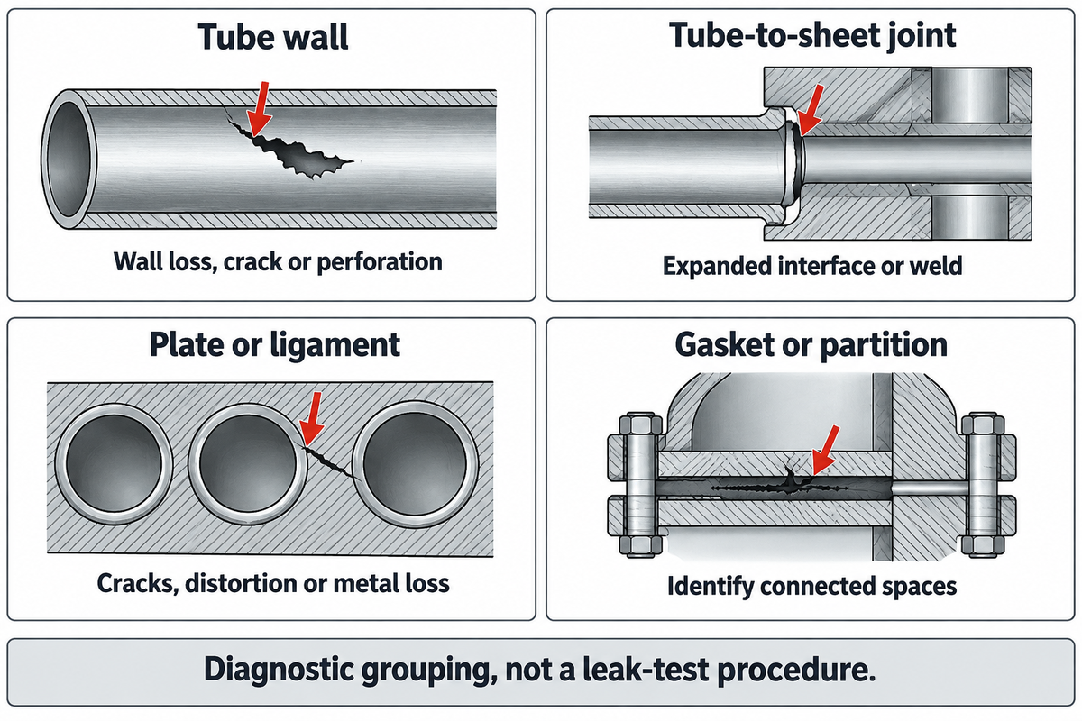
Failure of tube sheets and their joints happens due to corrosion, fatigue and fabrication damage. A leak near the plate can be from a tube wall or a gasket. Locating the true path prevents a repair team from rolling a joint where the defect isn’t located.
4-Path Leak Triage Matrix
A 4-path leak triage matrix is used to identify the possible causes of a leak before a repair method is chosen. The paths include tube wall, joints, plates and gaskets.
| Path | What to locate | Repair question |
|---|---|---|
| Tube wall | Wall loss, a crack or perforation near or away from the plate | Can the tube be repaired or plugged while retaining required duty? |
| Tube-to-sheet joint | Leakage at an expanded interface or welded joint | Is the joint under-expanded, cracked, corroded or already overworked? |
| Plate or ligament | Cracks, distortion, damaged overlay or local metal loss | Does the affected region retain the required structural capacity? |
| Gasket or partition | External leakage, sealing-face damage or internal pass bypass | Which spaces are connected by the failed seal? |
Pass-partition bypass may reduce heat exchange without allowing shell side contamination. This matrix is a diagnostic grouping, not a leak-test procedure. A gasket leak follows the particular flange and channel geometry.
In a 2016 failure investigation by Liu and colleagues, the tube material met the chemical and mechanical requirements for 304 stainless steel. The tube and tubesheet microstructures were normal, yet serious defects were found at the welded joint. Fatigue cracks initiated at those defects. The authors identified vibration or changing fluid temperature and pressure as possible sources of cyclic load. This tube-to-tubesheet failure analysis explains why a satisfactory material certificate doesn’t close a joint-failure investigation. The next work concerns the joint and its loading history, not simply replacing the assembly with the same material grade.
Can tube sheet heat exchangers leak?
Yes, leakage can occur at tube joints, through tube walls, through damaged plate regions or across seals. A pressure difference drives flow through an open path. A pressure test can be used to check leakage. It can’t remove fatigue damage, or determine the cause of recurring faults.
Deposits can conceal local attack and alter flow. High velocity or inlet impingement can also concentrate erosion in vulnerable areas. Our heat exchanger fouling guide covers deposits and cleaning separately from joint repair.
Inspecting and Repairing a Tube Sheet
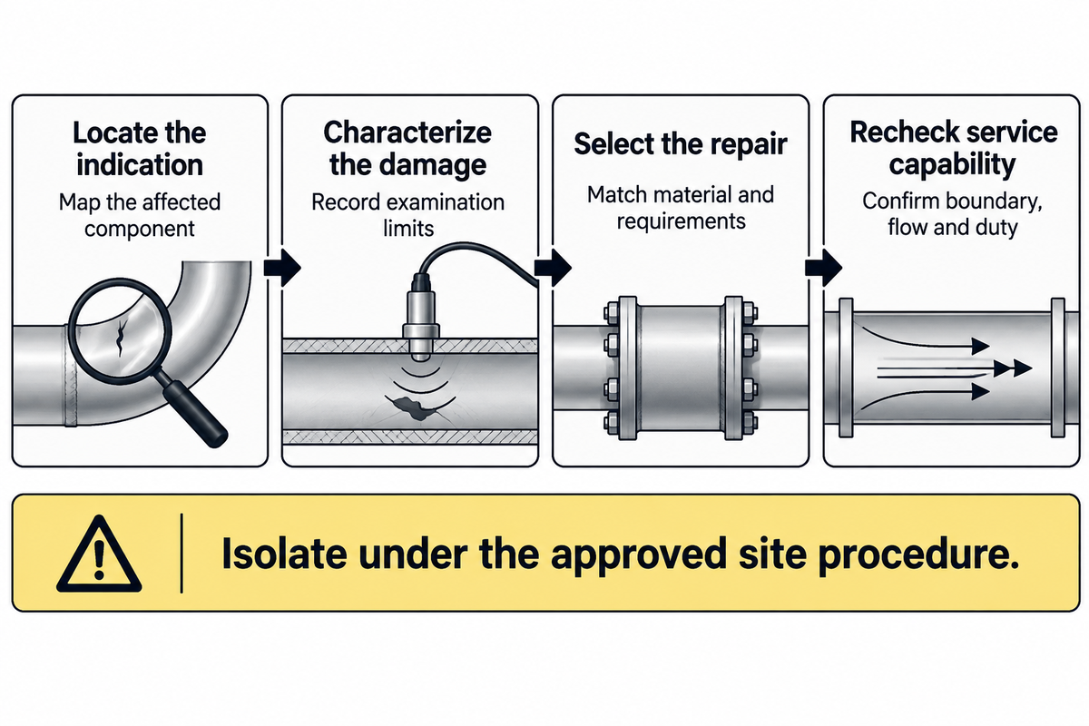
Use methods suited to the material and geometries of the components to determine the cause of damage, evaluate repairs, and assess joint integrity and functionality under duty. Visual inspection may reveal surface damage, staining, or iron oxide deposits, but tube-wall thinning and subsurface cracking may require other examination methods.
Before opening equipment: isolate both circuits, control stored pressure and temperature, and drain or decontaminate the unit under the site’s approved procedure. Pressure testing and pressure-boundary repairs require qualified personnel and an approved test or repair plan.
Cleaning exposes inspection surfaces but aggressive tooling can harm tube ends and cladding. A tube-side bundle cleaner removes deposits in accessible tubes; it doesn’t determine the soundness of a weld or ligament.
- Locate the indication. Map the affected tube, joint, ligament or sealing face.
- Characterize the damage. Use the qualified examination method and record its coverage and limits.
- Select the repair. Match the method to remaining material, joint construction and governing requirements.
- Recheck service capability. Evaluate the repaired boundary, flow path and available heat-transfer duty before return to service.
A 1999 Inspectioneering article by Reggie Cross describes the fabrication of a purpose-built ultrasonic fixture for cracking in a Ferrous tube-to-tubesheet weld. It details the significance of calibration and aiming the ultrasonic probes. A test adequate for one material, joint and hole configuration can’t be extrapolated to all cases.
Plugging removes a single tube from service. The remaining flow area and heating or cooling duty must meet the requirements of service. In the 2001 D.C. Cook inspection findings, the NRC noted a failure to assess plugging against exchanger differential pressure limits. After plugging, check differential pressure and the remaining duty against the exchanger’s limits instead of applying a fixed plugged-tube percentage.
National Board Interpretation 21-17, addressing the 2021 NBIC edition, distinguishes seal welding a mechanically installed tube plug from plugging a hole after the tube has been removed. Under that interpretation, the former can qualify as routine repair under specified conditions; the latter cannot. The editions of the NBIC and the jurisdiction in question determine the actual definition and repair route.
Repeated leakage, broad ligament damage or inadequate section remaining for a local repair may shift the focus toward retubing or replacement. The condition assessment should also include prior weld repairs and plug removal. A new sealing operation cannot resolve an unassessed structural defect behind it.
Tube Sheet Replacement Cost and Lead-Time Drivers
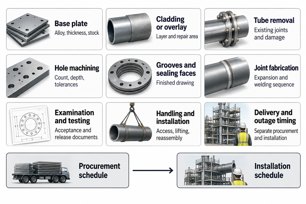
The cost of replacement is dependent on the type of plate material and geometry, the number and depth of holes, the type of joint work and extent of dismantling. Procurement lead time and installation duration are different parts of the schedule. A direct comparison of a quoted replacement bundle or complete site repair to a plate-only quotation isn’t valid.
| Cost category | What changes it | Quotation detail |
|---|---|---|
| Base plate | Alloy, thickness and stock availability | Material grade, dimensions and certification |
| Cladding or overlay | Layer material and affected repair area | Surface specification and examination |
| Hole machining | Hole count, depth and tolerances | Approved hole layout and finished dimensions |
| Grooves and sealing faces | Joint grooves, partition lanes and gasket seats | Finished drawing and dimensional inspection |
| Tube removal | Existing welds, expanded joints and damaged ends | Removal method and damage assessment |
| Joint fabrication | Expansion, welding and their sequence | Qualified joint procedure |
| Examination and testing | Joint geometry, test scope and hold points | Acceptance criteria and release documents |
| Handling and installation | Bundle access, lifting and reassembly | Site responsibilities and handling scope |
| Delivery and outage timing | Material release, shipping and field readiness | Separate procurement and installation dates |
The Heat Exchange Institute’s historical condenser comparison distinguishes module replacement from retubing and assigns a higher first cost and longer installation time for module replacement. New tubesheets can be included in a retube scope, so the name of the project doesn’t define the extent of work.
For a purchasing team, separate material release, machining, fabrication, examination and shipping dates from the shutdown work. An offer to fabricate an exchanger more quickly provides little shutdown time benefit if channel removal or lifting access remains undefined.
Information for a comparable repair quotation
- Send the exchanger drawing, tube layout and existing joint detail.
- State both-side design conditions, fluid chemistry and known damage history.
- Identify the plate, tube and cladding materials.
- Include the inspection findings and any plugged-tube map.
- Define examination, testing, documentation and return-to-service responsibilities.
- Ask for separate manufacturing, delivery and field installation schedules.
What the TEMA 2026 Edition Changes
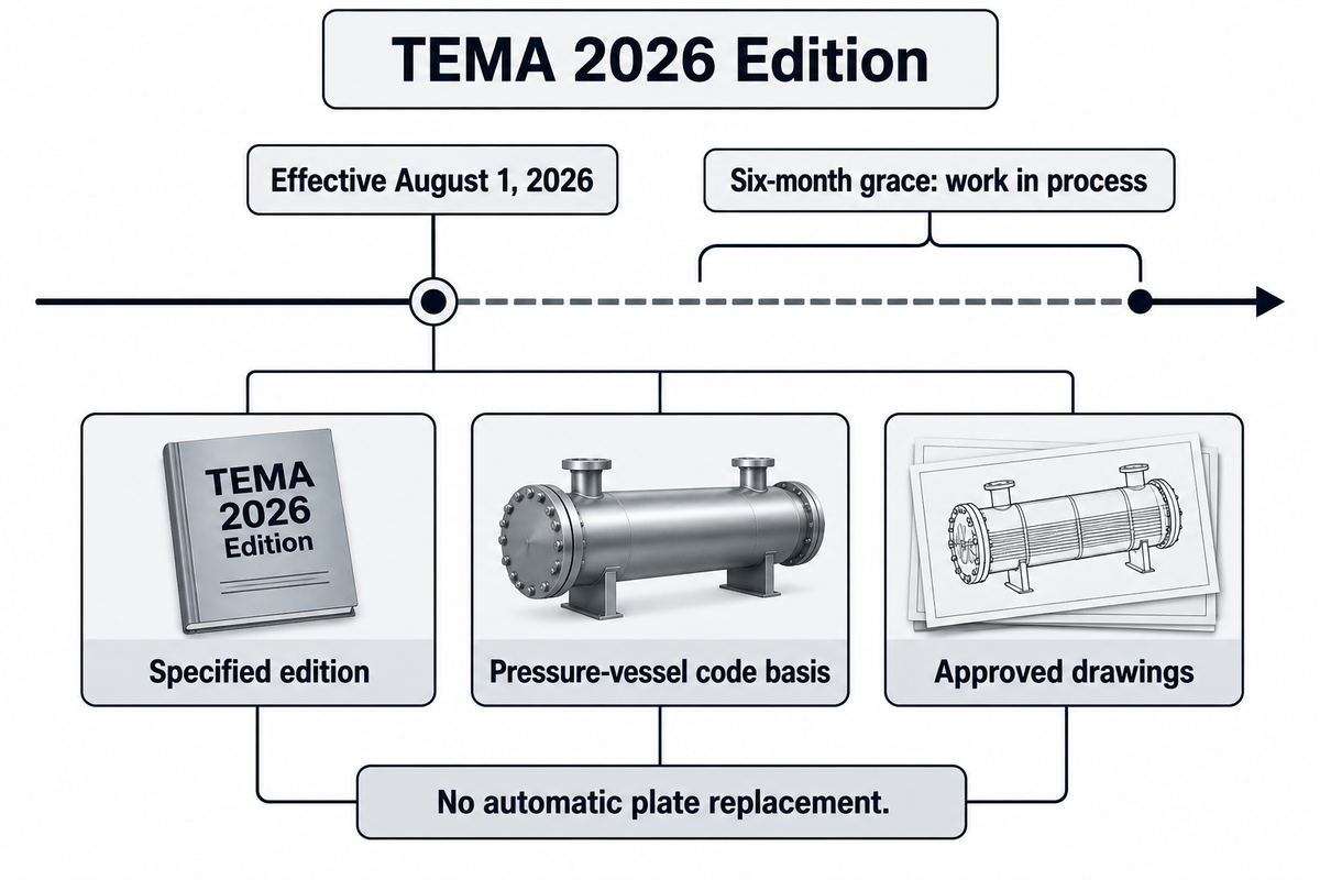
The TEMA 2026 edition changes the specification and construction information of new exchanger work. Effective August 1, 2026, TEMA granted a six-month grace period for work in process using the Eleventh Edition. Projects in this grace period need an explicit edition basis.
Information on the TEMA site lists updates to specification sheets and other content including U-bend supports and removable pass partitions in high-pressure channels. Construction details affect how assemblies are tied together and arranged, and extend well beyond the scope of the tubesheet plate.
TEMA’s support page explains the move from sequential edition numbers to publication years. The “2026 Edition” isn’t the Twelfth Edition. Standards are provided via online subscriptions and revised periodically, with notifications provided to subscribers.
For a replacement project, capture the specified edition in concert with the pressure-vessel code basis and approved drawings. A change to the publication year doesn’t mandate a replacement of the plate. Changes to the assembly being repaired still need to be assessed against the applicable repair and design criteria.
Work initiated during the transition should be specified to the same edition of the referenced standard. This prevents an older calculation basis, revised fabrication details and a specification sheet from being mixed without an engineering review.
Frequently Asked Questions
How do heat exchangers work?
Heat exchangers transfer thermal energy between fluids at different temperatures.
In a tubular unit, one fluid travels inside the tubes while another passes around them. Heat crosses the tube wall without intentional mixing of the two streams. Tube passes and baffles control the flow route. Increasing turbulence often increases the heat transfer rate, but also changes pressure drop. The tubesheet holds the ends and helps separate the circuits; it is not the main heat-transfer surface.
What materials are commonly used in heat exchanger tubes?
Common tube materials include carbon steel, stainless steel, copper alloys, titanium and nickel alloys.
Selection follows the fluids, temperatures and expected damage mechanisms. The tube material must also work with the tubesheet joint. Different alloys can change weldability, expansion response and corrosion resistance. Deposits and cleaning chemicals matter because the local environment around a tube end can differ from the bulk fluid. The plate and tube should therefore be evaluated together rather than selected from separate alloy rankings.
Why is a shell and tube heat exchanger used?
Shell-and-tube equipment accommodates many industrial fluid duties through different materials, pressure designs and maintenance arrangements.
The designer can select the tube alloy and joint construction while choosing a layout for thermal movement and cleaning access. A removable bundle permits access that a fixed assembly may restrict. High pressure service requires an appropriate pressure design, and high heat transfer performance requires suitable flow and surface area. A compact arrangement alone does not settle the material, inspection or cleaning requirements.
Where are shell and tube heat exchangers used?
Shell-and-tube exchangers serve heating, cooling and condensing duties in chemical processing, refining and power generation.
Industrial applications vary in fluid cleanliness and maintenance access. A cooling-water service and a corrosive process service can require very different tube joints and materials.
Is a tube sheet the same as a baffle?
No. A tubesheet secures tube ends at a fluid boundary; a baffle supports tubes within the shell and can direct shell-side flow.
Both parts can contain holes through which tubes pass, so their perforated appearance can be misleading. Look at their position and the way the tubes are attached. Tubes are attached to the tube sheet by the specified expanded or welded joints. Intermediate baffles normally allow one shell-side fluid to move around them instead of sealing that fluid from the tube side. A baffle layout can influence velocity and vibration, while the end plate also carries the tube-end connections and pressure-boundary loads. Their dimensions and acceptance criteria therefore serve different functions.
Plan the handling work around the repair scope
For a removable bundle, define extraction access and handling requirements before the shutdown. Contact BOSHIYA about bundle handling equipment with the exchanger drawing and site access details.
This guide incorporates published technical guides, research and historical inspection cases. The leak-triage matrix is an editorial tool for diagnosing leak paths. Acceptance and repair of pressure-boundary leaks remain specific to the exchanger and its governing requirements.
References & Sources
- Heat Exchangers to Avoid Contamination, U.S. Food and Drug Administration, 1979.
- Stainless Steel in Contact with Other Metallic Materials, Euro Inox, 2009.
- Steam Generator Channel Head and Tubesheet Degradation, U.S. Nuclear Regulatory Commission, Information Notice 2013-20.
- Tubesheets for U-Tube Heat Exchangers, Singh and Soler, 1984, public chapter abstract.
- Failure Analysis of Tube-to-Tubesheet Welded Joints, Liu and colleagues, 2016, City University of Hong Kong research record.
- UT Inspection for Cracking in Tube-to-Tubesheet Welds, Reggie Cross, Inspectioneering, 1999.
- D.C. Cook 2 Inspection Findings, U.S. Nuclear Regulatory Commission, 2001.
- NBIC Interpretations, Interpretation 21-17, National Board of Boiler and Pressure Vessel Inspectors.
- Condenser Modular Replacement vs. Retube, Heat Exchange Institute, Tech Sheet 122, 2007.
- TEMA Standards 2026, Tubular Exchanger Manufacturers Association.
- TEMA Standards Support and Edition Transition, Tubular Exchanger Manufacturers Association.