Get in Touch with BOSHIYA


Industrial urea production converts liquid ammonia (NH 3 ) and compressed carbon dioxide (CO 2 ) into solid nitrogen fertilizer. This manufacturing process operates at 180-200 °C and 140-250 atm, using the two-step Bosch-Meiser synthesis route. Note that this engineering guide covers chemical fertilizer manufacturing rather than the biological ornithine-urea cycle in mammalian livers. Urea is an organic compound with the chemical formula CO(NH 2 ) 2 . It’s widely used as a fertilizer due to its high nitrogen content of 46% by weight, making it one of the most efficient widely used nitrogen fertilizers in agriculture.
Contents
show
Engineering parameters at a glance
- Synthesis window: Reacting ammonia with carbon dioxide at 180–200 °C (356–392 °F) and 140–250 atm (14,185–25,331 kPa). Commercial reactors maintain an NH3:CO2 molar ratio of 3:1 to 4:1.
- Single-pass equilibrium: Per U.S. EPA AP-42 and thyssenkrupp Uhde specifications, ammonium carbamate dehydration reaches 55%–68% CO2 conversion per pass. Subsequent high-pressure stripping yields a 70–77 wt% urea solution concentration.
- Brouwer / UreaKnowHow reports a passive corrosion rate of 0.12 mm/year for modified 316L Urea Grade (UNS S31603) at 5–7.3 ppm liquid-phase dissolved O2 under the reported test conditions. In those same test conditions, corrosion jumps to 30–40 mm/year in the active state at 0.5–3 ppm O2.
- Finishing routes: Prilling towers solidify 99.5–99.8 wt% molten urea into 1.5–2.2 mm prills. Fluid-bed granulators layer 96–98.5 wt% melt into 2.0–4.0 mm granules.
Fortune Business Insights valued the global urea market at USD 85.33 billion in 2025. In commercial plants, the major reliability issues are single-pass reactor equilibrium, carbamate condenser corrosion, vacuum evaporation biuret formation and finishing dust recovery. Below, our 1,000-Tonne Urea Synthesis & Recycle Mass-Balance Worksheet, quantifies reactor to stripper recycle loads. In addition, the 9-Zone Urea Process Corrosion & Fouling Diagnostic Matrix maps alloy selection and turnaround bundle maintenance across the plant.
In industrial urea production, anhydrous liquid ammonia and gaseous carbon dioxide react at 180–200 °C and 140–250 atm to form ammonium carbamate. Ammonium carbamate partially dehydrates to urea and water; subsequent stripping removes unconverted reactants to yield a 70–77 wt% aqueous urea solution. Unreacted gases are stripped and recycled, while vacuum evaporation concentrates the melt for prilling or granulation into 46-0-0 solid urea.
Key takeaways
- Producing 1 metric ton of pure urea requires 567 kg of NH3 and 733 kg of CO2 by stoichiometry. Commercial plants consume 570–580 kg NH3 and 740–750 kg CO2 per ton.
- Stamicarbon CO2 stripping loops operate near 140–145 bar and 180 °C (N/C ≈ 3.0). Saipem NH3 self-stripping loops run at 150–155 bar and 185–210 °C (N/C = 3.3–3.6).
- ASTM A262 Practice C qualifies intergranular attack resistance in austenitic steels (UNS S31603 and UNS S31050). Super-duplex Safurex (<0.01 mm/year) and bimetallic Zr/Ti tubes handle low-oxygen stripping duties.
- Prills solidify from the outer shell inward and form an internal shrinkage cavity (3.80 N sample failure load). Layered fluid-bed granules reach 10–17 N in laboratory tests.
- Agricultural-grade urea conditioned with 0.2–0.5 wt% urea-formaldehyde additive can cause a 32.5 wt% urea solution to exceed the ISO 22241-1 aldehyde limit of 5 mg/kg for Diesel Exhaust Fluid (DEF / AUS 32).
How Ammonia and Carbon Dioxide Become Urea: The Two-Step Bosch-Meiser Reaction
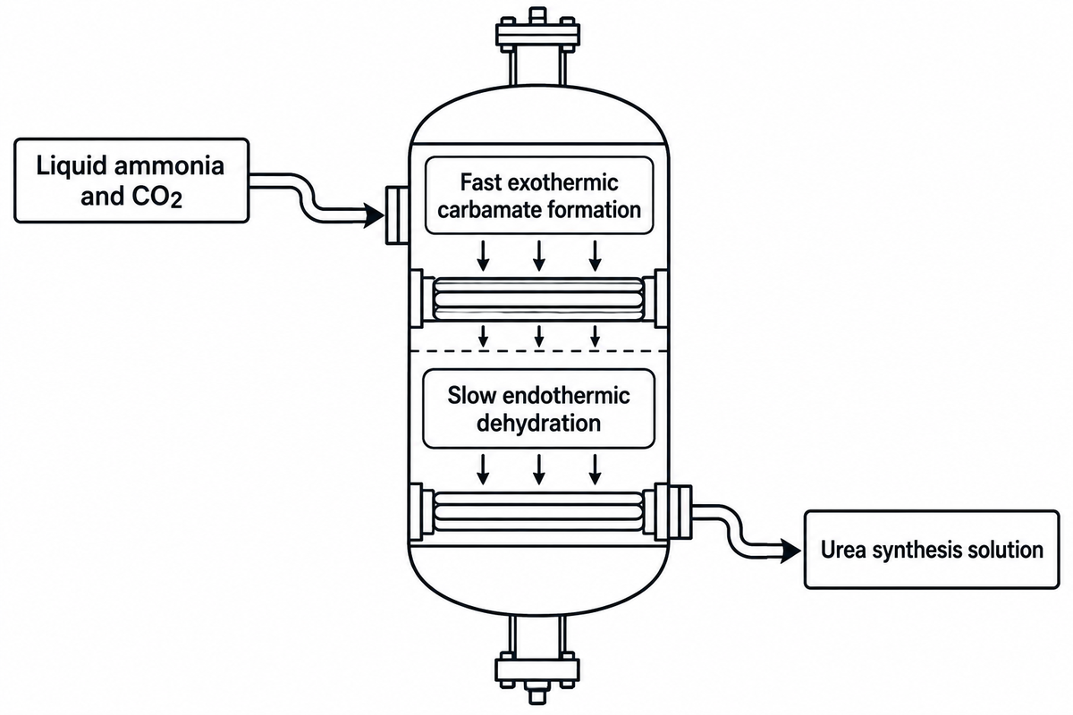
First commercialized in 1922, the Bosch-Meiser process produces industrial urea through two reversible steps: liquid ammonia and gaseous carbon dioxide form ammonium carbamate, which then dehydrates into urea and water. The industrial process route is referred to as the Bosch-Meiser process, where urea is synthesized by reacting liquid ammonia and gaseous carbon dioxide in a lined high-pressure synthesis reactor. Ammonia and carbon dioxide won’t form urea in a single step. Instead, this reversible chemical reaction combines both reactants under high pressure and temperature to yield ammonium carbamate which is a crystalline chemical compound. Controlled vapor-liquid equilibrium governs its subsequent conversion to urea and water.
As described in U.S. EPA AP-42 Section 8.2 (Urea) and U.S. EPA HERO thermodynamic reference 2009046, synthesis reactors operate at 180 to 200 °C (356 to 392 °F). Reactor pressures range from 140 to 250 atm (14,185 to 25,331 kPa). Reactants enter at an NH 3 :CO 2 molar ratio (N/C) of 3:1 to 4:1 with a liquid retention time of 20 to 30 minutes. Two sequential reactions take place inside the synthesis vessel.
Step 1 (Fast Exothermic Carbamate Formation): 2 NH3 + CO2 ↔ NH2COONH4 (ΔH ≈ −117 kJ/mol)
Step 2 (Slow Endothermic Dehydration to Urea): NH2COONH4 ↔ CO(NH2)2 + H2O (ΔH ≈ +15.5 to +32 kJ/mol)
Step 2 (Slow Endothermic Dehydration to Urea): NH2COONH4 ↔ CO(NH2)2 + H2O (ΔH ≈ +15.5 to +32 kJ/mol)
Step 1 is fast and strongly exothermic. It releases roughly 117 kJ/mol as ammonia and carbon dioxide condense to form ammonium carbamate. Step 2 is slow, endothermic, and equilibrium-limited. Dehydration of ammonium carbamate to urea is accomplished by removal of one mole of water. According to thyssenkrupp Uhde’s pool-condenser synthesis specification, in commercial stripping reactors, the single pass CO2 conversion is in the range of 55% to 68%.
Why does single-pass conversion stop near 60%? Step 2 is a reversible dehydration reaction. For every mole of water that gets incorporated in the reactor or returns with recycled carbamate wash liquor, the position shifts equilibrium toward unreacted carbamate. Raising the N/C molar ratio from 2.0 (stoichiometric) to 3.0–3.6 drives CO2 conversion higher. Keeping the H2O:CO2 molar ratio (H/C) low preserves the dehydration driving force.
Explicit boundary and assumptions for the 1,000-Tonne Urea Synthesis & Recycle Mass-Balance Worksheet
All figures below represent a transparent stoichiometric and single-pass equilibrium engineering calculation for a 1,000 metric ton per day (MTPD) urea synthesis unit. They aren’t proprietary operating logs from a private plant. Molar masses used are urea = 60.06 g/mol, NH3 = 17.03 g/mol, CO2 = 44.01 g/mol, H2O = 18.015 g/mol, and ammonium carbamate = 78.07 g/mol. The industrial case modeled here assumes a nominal reactor at 180 °C, 145 bar, and N/C molar ratio = 3.0 (50% molar excess NH3). It models nominal 60.0% single-pass CO2 conversion and 99.0% overall loop recovery after high-pressure stripping and low-pressure recycling.
| Stream / Mass-Balance Parameter | Unit | Theoretical Complete Single-Pass (N/C = 2.0) | Modeled Stripping Reactor (Nominal 60% Pass, N/C = 3.0) | Engineering & Recycle Impact |
|---|---|---|---|---|
| Net urea produced (anhydrous dry basis) | t / day | 1,000.0 | 1,000.0 (16.65 Mmol) | Fixed product output benchmark |
| Fresh make-up liquid NH3 feed | t / day | 567.1 | 572.8 (incl. ~1% loop loss) | 0.567 t stoichiometric (0.57–0.58 t typical plant) |
| Fresh make-up gaseous CO2 feed | t / day | 732.8 | 740.1 (incl. ~1% loop loss) | 0.733 t stoichiometric (0.74–0.75 t typical plant) |
| Total CO2 equivalent entering reactor | t / day | 732.8 | 1,221.3 (27.75 Mmol modeled in nominal 60% pass) | CO2-equivalent recycle equals 1,221.3 minus 740.1 t/day fresh make-up (481.2 t/day net recycle) |
| Total NH3 equivalent entering reactor | t / day | 567.1 | 1,417.8 (83.25 Mmol at N/C = 3.0) | Total NH3-equivalent reactor feed is 1,417.8 t/day (83.25 Mmol at N/C = 3.0); the NH3-equivalent recycle equals this total minus 572.8 t/day of fresh make-up (845.0 t/day net recycle) |
| Reaction water generated in Step 2 | t / day | 300.0 | 300.0 (16.65 Mmol H2O) | Water is removed during concentration; residual urea in the process condensate is hydrolyzed, and ammonia and CO2 are recovered by stripping. |
| Unconverted ammonium carbamate leaving reactor | t / day | 0.0 | 866.6 (11.10 Mmol NH2COONH4) | Decomposed in HP stripper & LP recovery stages |
| Unreacted free excess NH3 leaving reactor | t / day | 0.0 | 472.6 (27.75 Mmol free NH3) | Stripped and condensed in HP carbamate condenser |
| Total reactor liquid effluent to HP stripper | t / day | 1,300.0 | 2,639.2 (plus recycle water) | Governs falling-film stripper tube count and duty |
| Total carbamate + NH3 recycle load | t / day | 0.0 t/d | 1,326.2 t/d net recycled (1,339.2 t/d unconverted) | After loop losses, the recycle contains 481.2 t/day of CO2 equivalent and 845.0 t/day of NH3 equivalent, totaling 1,326.2 t/day on the table’s stated feed basis. |
Feedstock Integration: Why Urea Plants Sit Next to Haber-Bosch Ammonia Units
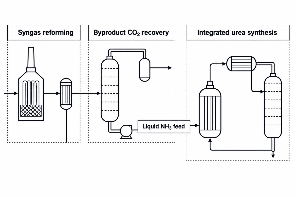
Commercial urea plants almost never operate as standalone chemical facilities because integrated Haber-Bosch hydrocarbon reforming supplies both hydrogen for ammonia and byproduct carbon dioxide for urea. The integrated operation of the Haber-Bosch hydrocarbon reforming furnishes both H2 for the ammonia and byproduct carbon dioxide for urea synthesis, and gives a distinct economic advantage. The unit with raw material gas preparation is located adjacent to the Haber-Bosch ammonia unit. As detailed in Montana State University Agricultural Marketing Policy Center Briefing No. 112, hydrocarbon reforming generates two outputs simultaneously. It supplies H2 to produce ammonia and concentrated byproduct carbon dioxide to produce urea.
Is urea made from natural gas, coal, or petroleum?
Most of the world’s urea is derived from natural gas through steam methane reforming or from coal through gasification, the predominant method in China. Heavy fuel oil and petroleum naphtha represent a small, legacy share. Hydrocarbon reforming provides both the hydrogen needed to synthesize ammonia and the captive carbon dioxide required for urea synthesis.
In an integrated complex supplying ammonia and urea for fertilizer production, natural gas (CH4) or gasified coal reacts with steam and air/oxygen. This reforming step generates synthesis gas containing H2, CO, and CO2. Water-gas shift reactors then convert CO and steam into additional H2 and CO2. Before the gas stream enters the Haber-Bosch ammonia reactor, an acid-gas removal unit scrubs the syngas. Using alkanolamine (MDEA) or hot potassium carbonate solutions, it recovers CO2 at 98.5%–99.5% purity.
As disclosed in WO2025155218A1, the CO2 is compressed to 140-160 bar (approx. 2,031-2,321 psi). Before entering the high-pressure synthesis loop, the CO 2 feed passes three quality control checkpoints:
- Total sulfur removal: Sulfur compounds poison catalytic hydrogen-removal beds and accelerate active corrosion on stainless-steel stripper tubes.
- Catalytic hydrogen removal: Recovered CO2 can contain hydrogen carried through acid-gas removal; catalytic hydrogen removal reduces the risk of hydrogen accumulating with oxygen in the synthesis loop. A platinum or palladium catalytic reactor oxidizes residual H2 to water before final compression.
- Controlled passivation oxygen dosing: Measured air or oxygen is injected into the CO2 compressor suction so dissolved oxygen maintains the passive oxide film on high-pressure stainless-steel equipment.
| Feedstock & Reforming Route | Primary Regions | Captive CO2 Balance per Tonne NH3 | Impact on Urea Synthesis Loop |
|---|---|---|---|
| Natural Gas Steam Methane Reforming (SMR) | North America, Middle East, Russia, Europe | ~1.15–1.25 t process CO2 captured per t NH3 (~1.29 t CO2 needed for full conversion to urea) | The captured process CO2 supports approximately 89.1%–96.9% conversion of NH3 capacity to urea; optional flue-gas CO2 recovery closes the balance. |
| Autothermal Reforming (ATR) / Gas POX | Large-scale mega-plants & blue ammonia hubs | Higher process-gas CO2 share captured at elevated pressure | Oxygen-fed ATR and gas POX require an oxygen supply, commonly from an air separation unit; air-fed ATR introduces nitrogen with the process air. |
| Coal Gasification (Anthracite / Bituminous) | China (dominant domestic route) | >2.0–2.8 t process CO2 generated per t NH3 (substantial CO2 surplus) | Requires deep sulfur removal; Rectisol and Selexol are established acid-gas removal options. |
| Electrolytic Green Hydrogen + N2 | Emerging renewable fertilizer projects | 0.0 t captive CO2 (complete stoichiometric carbon deficit) | Requires an external CO2 supply for urea synthesis; captured industrial CO2, biogenic CO2, and direct-air-captured CO2 are possible feedstocks. |
High-Pressure Synthesis Loops Compared: CO2 Stripping vs. NH3 Self-Stripping
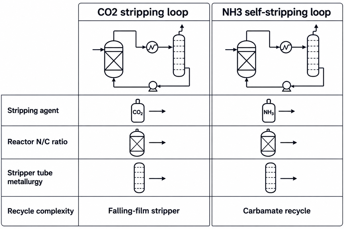
Early complete-recycle urea plants decomposed unconverted carbamate by depressurizing the entire reactor effluent to medium and low pressure. That layout consumed lots of steam and electric power to pump the carbamate solution back to 200 bar. Later urea manufacturing eliminated this energy penalty through high-pressure stripping. Unconverted ammonium carbamate is decomposed at the same pressure as the synthesis reactor in an isobaric loop.
How does CO2 stripping compare with NH3 self-stripping in a urea synthesis loop?
CO2 stripping (Stamicarbon / Uhde) uses counter-current CO2 gas to strip reactor effluent at 140-145 bar (N/C ≈ 3.0), whereas NH3 self-stripping (Saipem) uses thermal heating and excess ammonia at 150-155 bar (N/C = 3.3-3.6).
According to Stamicarbon’s high-pressure stripper design specification, Chemical Engineering’s analysis of the NH3 self-stripping process and Mark Brouwer’s UreaKnowHow synthesis loop comparison, three licensor architectures prevail in modern capacity:
- CO2 Stripping Process (Stamicarbon / thyssenkrupp Uhde, >50% licensing share): Operates at an optimum synthesis pressure of 140–145 bar (14.0–14.5 MPa) and 180–185 °C with an N/C molar ratio of 2.95–3.1. Reactor solution flows down a vertical falling-film shell-and-tube stripper heated on the shell side by 20–25 bar steam. Counter-current fresh gaseous CO2 strips out NH3 and CO2 by reducing NH3 partial pressure. Overhead gases condense in a high-pressure pool condenser or vertical carbamate condenser, raising 4.5–5.5 bar steam for evaporation.
- NH3 Self-Stripping Process (Saipem / Snamprogetti, ~35% licensing share): Operates at 150–155 bar and N/C = 3.3–3.6. All fresh CO2 enters the reactor directly rather than entering the stripper. The falling-film stripper uses shell-side high-pressure steam (reaching 205–210 °C at the stripper bottom) so dissolved excess ammonia boils out and strips decomposed CO2. A high-pressure liquid-ammonia-driven ejector circulates carbamate from the condenser back to the reactor without moving mechanical parts.
- Toyo Engineering’s ACES21 process uses CO2 stripping and carbamate condensation; UreaKnowHow reports approximately 145–155 bar, N/C = 3.7–4.0, and ~15% global licensing share for this process.
Recent synthesis patent disclosures refine this high-pressure envelope further. WIPO Patent Application WO2025155218A1 (2025) and USPTO Patent Application US20120302789A1 operate the reactor at 14.0–16.0 MPa and 170–190 °C, the stripper at 180–210 °C, and the carbamate condenser at 160–170 °C. Adding pre-reactors and optimizing low-pressure recovery at 2–6 bar reduces steam consumption.
| Loop Parameter | CO2 Stripping (Stamicarbon / Uhde) | NH3 Self-Stripping (Saipem) | ACES21 CO2 Stripping (Toyo) |
|---|---|---|---|
| Approximate global licensing share | >50% of stripping plants | ~35% of stripping plants | ~15% of stripping plants |
| Synthesis loop pressure | 140–145 bar (14.0–14.5 MPa) | 150–155 bar (15.0–15.5 MPa) | 145–155 bar (14.5–15.5 MPa) |
| Reactor operating temperature | 180–185 °C | 185–190 °C | 182–190 °C |
| Stripper bottom temperature | 180–185 °C (CO2 stripper envelope) | 205–210 °C (thermal stripping) | 185–195 °C |
| Reactor NH3:CO2 molar ratio (N/C) | 2.95–3.10 | 3.30–3.60 | 3.70–4.00 |
| Primary stripping agent in HP stripper | Counter-current fresh CO2 feed gas | Boiled excess NH3 (thermal self-strip) | Counter-current CO2 + internal trays |
| HP loop circulation driver | Elevation head or thermosyphon density difference; liquid-ammonia ejector in ejector-assisted configurations | HP liquid-NH3-driven carbamate ejector | Elevation head or HP carbamate ejector |
| Downstream carbamate recovery stages | Single LP recovery stage (~3–5 bar) | MP stage (~17–20 bar) + LP stage (~3–5 bar) | MP + LP recovery with heat integration |
| Typical HP stripper tubing metallurgy | 25Cr-22Ni-2Mo (UNS S31050) or Safurex | Bimetallic 25-22-2/Zr or OmegaBond Zr/Ti | Duplex DP28W or 25Cr-22Ni-2Mo |
Carbamate Condensers, Strippers, and High-Pressure Metallurgy: Preventing Active Corrosion
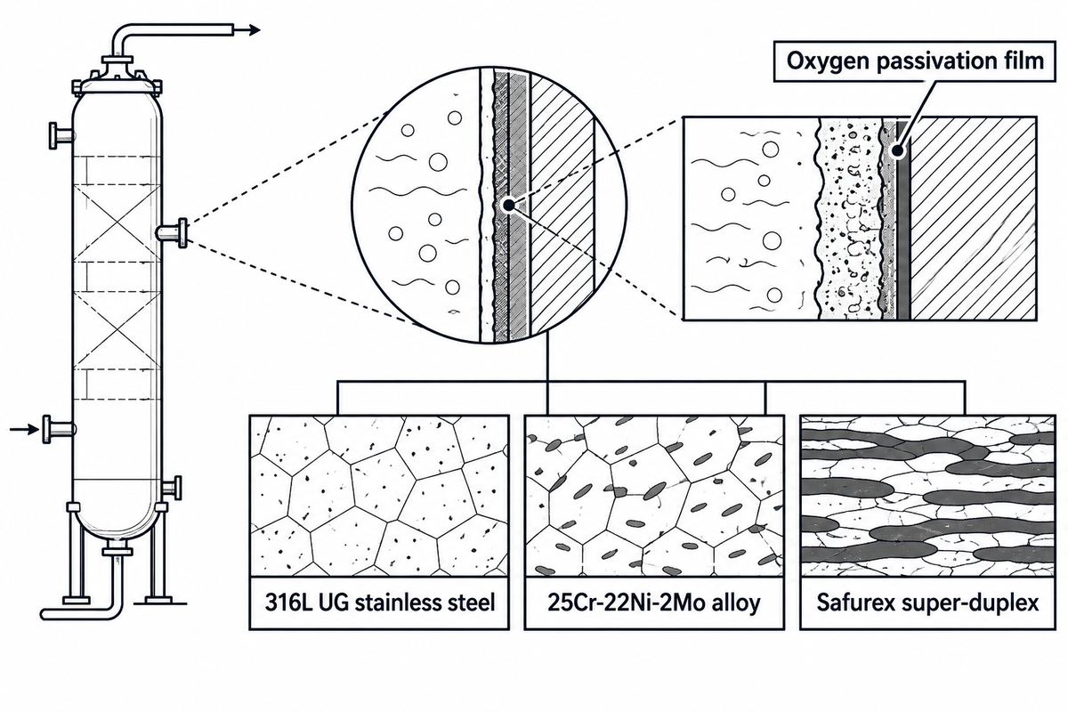
Hot aqueous ammonium carbamate at 180-210 °C and 140-250 bar is one of the most aggressive process fluids in the chemical industry. Standard commercial 304L or 316L stainless steels corrode rapidly in high-pressure carbamate service. Selective inter-granular attacks lead to dissolution of delta-ferrite phases and depleted-grain-boundary molybdenum.
To prevent vessel or heat-exchanger failure, high-pressure urea reactors, falling-film strippers, and carbamate condensers rely on specialized alloys. These grades are documented in UreaKnowHow’s metallurgical review of stainless steels in urea plants and Alleima’s high-pressure urea stripper tube specifications:
- Modified 316L Urea Grade (UNS S31603 / 3R60 UG): UreaKnowHow reports a maximum ferrite limit of ≤0.6% for this grade. Mills qualify it via the ASTM A262 Practice C (Huey) boiling 65% nitric acid test (five 48-hour periods) at ≤0.60 mm/year to screen intergranular attack susceptibility.
- 25Cr-22Ni-2Mo Austenitic Steel (UNS S31050 / WSN 1.4466 / 2RE69): Per Alleima and UreaKnowHow, this grade nominally contains 25% Cr, 22% Ni, and 2% Mo for stripper tubes and carbamate condenser bundles. Under Brouwer / UreaKnowHow’s test conditions, dropping dissolved oxygen from 5–7.3 ppm to 3 ppm shifted UNS S31603 from 0.12 mm/year (passive) to 30–40 mm/year (active corrosion). By contrast, UNS S31050 stayed passive at 0.03 mm/year down to 3 ppm O2 before turning active (10 mm/year) at 0.5–1 ppm O2.
- Super-Duplex Safurex (29Cr-6.5Ni-2Mo-N): In Heat Exchanger World’s Safurex study, super-duplex Safurex shows a general carbamate corrosion rate below 0.01 mm/year. It also resists steam-side chloride stress corrosion cracking (SCC), while loop oxygen dosing still accounts for all wetted circuit materials.
- Bimetallic Zirconium and OmegaBond (Zr/Ti) Stripper Tubes: Used in Saipem NH3 self-strippers where bottom temperatures reach 205–210 °C. UreaKnowHow reports that mechanical bimetallic tubes (a Zirconium inner liner inside a 25-22-2 outer tube) achieve a 10–15 year stripper life, versus 20–25 years for other HP vessels. Operators often flip mechanical bimetallic strippers after 6–8 years. OmegaBond tubes use a metallurgical bond between zirconium and titanium to eliminate the unbonded interfacial crevice. UreaKnowHow describes solid-state extrusion below 50% of the melting point without specifying the reference metal or temperature scale.
Past tube selection, Heat Exchanger World’s review of shell-and-tube weld overlay cladding outlines carbon-steel tubesheet cladding rules. Heat Exchanger World describes tubesheet weld-overlay cladding with a minimum 1.5 mm depth of undiluted corrosion-resistant alloy, citing API Std. 660 and the use of buffer (“butter”) passes to control substrate dilution. WIPO Patent Application WO2025206949A1 (2025) shows that the erosion of metallic liquid dividers causes incomplete wetting of the film and dry (oxygen deprived) spots, which is the motivation behind using ceramic liquid dividers. On Eng-Tips HP urea loop inspection threads, plant engineers discuss the frequency of inspections performed on high-pressure urea vessels and exchanger bundles during turnaround. The 9-Zone Urea Process Corrosion & Fouling Diagnostic Matrix below covers nine equipment zones, linking mechanisms of deterioration to operational indicators and maintenance actions. For basic exchanger design and deposit mechanisms, refer to our tube-sheet heat exchanger design and inspection guide, industrial heat exchanger fouling mechanisms guide, and automated tube bundle extraction and cleaning systems.
| Loop Stage & Equipment Zone | Operating Envelope & Fluid | Primary Corrosion / Fouling Mode | Online Indicator & Turnaround Action |
|---|---|---|---|
| 1. HP Reactor Loose Liner & Weep Holes | 180–200 °C, 140–250 bar urea + carbamate | Active weld-zone corrosion or liner pinhole attack on 316L UG / Safurex | Continuous NH3/CO2 leak detection on shell weep holes; dye-penetrant weld audit |
| 2. HP Stripper Top Liquid Divider & Ferrule | 180–190 °C two-phase reactor effluent entry | Distribution hole erosion causing uneven film wetting and dry-spot attack | Rising stripper outlet NH3 slip; inspect tangential holes or upgrade to ceramic divider |
| 3. HP Falling-Film Stripper Tube Bundle | 185–210 °C falling carbamate film + HP steam shell | Active corrosion (30–40 mm/yr on 316L UG if O2 starved) or bimetallic crevice attack | Lab Ni/Cr/Fe ppm in urea product + tube wall NDE inspection matched to alloy permeability during turnarounds |
| 4. HP Stripper Tubesheet Weld Overlay | Determine tubesheet overlay temperature from equipment design basis (180–210 °C applies to stripper carbamate solution in WO2025155218A1) | Carbon-steel dilution during overlay welding can lower corrosion-resistant alloy content at the process-facing surface; Heat Exchanger World cites API Std. 660 for a minimum 1.5 mm undiluted depth | Ferritescope check for low ferrite content on 316L UG overlays plus boroscope weld root and dye-penetrant inspection |
| 5. HP Carbamate / Pool Condenser U-Bundle | 160–180 °C condensing gas vs. 4.5–5.5 bar LP steam | Shell-side chloride SCC on austenitic tubes + baffle fretting wear | LP steam conductivity/NH3 spike; specify Safurex duplex tubes + BFW chloride control |
| 6. MP / LP Decomposer Heater Exchangers | 135–165 °C at 2–20 bar carbamate decomposition | Two-phase carbonate/bicarbonate flashing erosion and iron-oxide fouling | Wide temperature approach; hydroblast removable bundle at pressure rated for tube metallurgy and remaining wall thickness (cleaning systems rated up to 40,000 PSI) |
| 7. Vacuum Evaporator Surface Condensers | 60–140 °C under 0.03–0.35 bar abs vacuum | Solid urea entrainment crusting + cooling-water carbonate scaling | Loss of vacuum (rising absolute pressure) + biuret creep; condensate flush + bundle clean |
| 8. Process Condensate Hydrolyzer Feed Exchanger | 180–230 °C, 15–35 bar dilute NH3/CO2/urea water | Dilute ammonium carbamate / carbonate corrosion at weld heat-affected zones | Stripped effluent NH3/urea >5 ppm; pressure test shell-and-tube interchanger |
| 9. Prilling / Granulation Wet Scrubber Coolers | 40–80 °C recirculated urea liquor + acid scrub | Crystallized urea-formaldehyde polymer and dust sludge plugging | Scrubber ΔP rise; warm condensate wash + high-pressure tube lancing |
Vacuum Concentration, Biuret Control, and Process Condensate Treatment
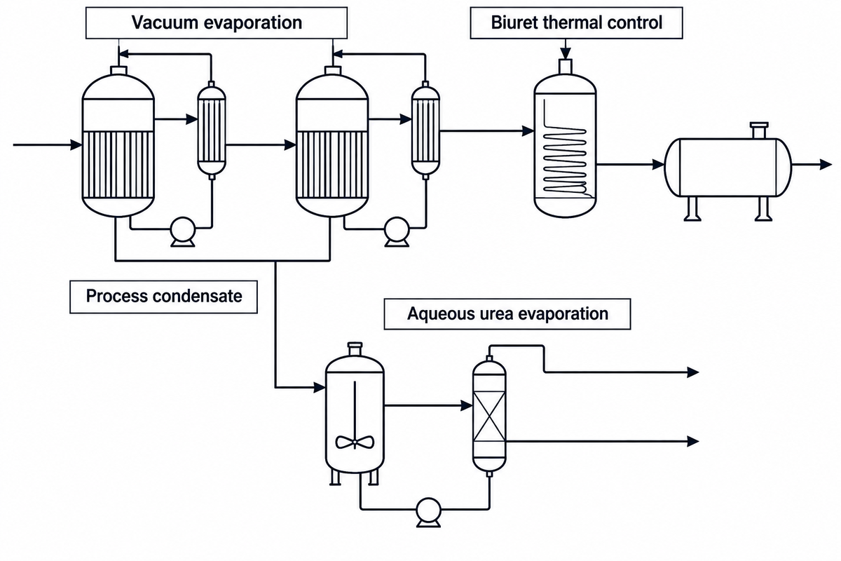
After stripping and downstream recovery decompose residual ammonium carbamate and remove ammonia and carbon dioxide, the aqueous solution contains 70 to 77 wt% urea. Converting that solution into solid urea requires evaporating the remaining water without overheating the melt. As noted in U.S. EPA AP-42 Section 8.2, aqueous urea solution begins decomposing thermally above 60 °C (140 °F) into biuret (NH2CONHCONH2) and free ammonia. Dimerization accelerates sharply near and above the 132.7 °C pure urea melting point:
Thermal Biuret Dimerization: 2 CO(NH2)2 ↔ NH2CONHCONH2 (Biuret) + NH3 ↑
Why is biuret strictly policed in fertilizer manufacturing? Excess biuret is phytotoxic to germinating seeds and citrus or pineapple foliage. Agricultural 46-0-0 identifies the fertilizer’s nutrient grade; low-biuret urea is used for sensitive foliar applications. Meanwhile, automotive ISO 22241-1 limits biuret to ≤0.3 wt% in finished 32.5 wt% aqueous AUS 32 solution. High temperature and prolonged liquid residence time accelerate biuret formation, so plants concentrate the 74 wt% urea solution across two vacuum evaporation stages. Stage 1 operates at 0.25–0.35 bar abs (~95 wt%), and Stage 2 operates at 0.03–0.06 bar abs and 138–140 °C with seconds-scale residence time. This yields 96–98.5 wt% melt for granulation or 99.5–99.8 wt% melt for prilling.
Evaporating 300 kg of reaction water per metric ton of urea also generates contaminated process condensate. It contains 1–6 wt% dissolved NH3, CO2, and entrained urea. In EPA AP-42 Table 8.2-1, the uncontrolled solution-formation and concentration ammonia emission factor is 9.23 kg/Mg (18.46 lb/ton). Instead of venting or discharging this stream, modern plants route process water through a steam-heated deep hydrolyzer at 180–230 °C and 15–35 bar. The hydrolyzer converts residual urea into ammonia and carbon dioxide (CO(NH2)2 + H2O → 2NH3 + CO2), and associated desorption equipment removes the resulting gases.
Finishing the Melt: Prilling Towers vs. Fluid-Bed Granulation
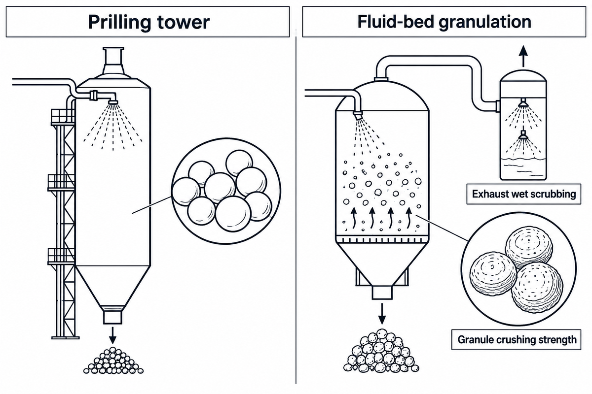
The final finishing steps of the urea production process convert concentrated molten urea into free-flowing solid particles via prilling, granulation, and protective solids coating. Older plants favored natural-draft or forced-draft prilling towers for their lower capital cost and low power demand. By contrast, modern export complexes predominantly install fluidized-bed granulators to produce modern urea fertilizer with superior crushing strength.
A counterintuitive mechanical insight is documented by Kreber’s engineering comparison of prilling and granulation and measured in White Rose University’s Procedia Engineering study (Rahmanian et al., 2015). It explains why prills can’t match granule crushing strength simply by increasing droplet size:
- Inward solidification and the prill shrinkage cavity: In a prilling tower, near-anhydrous 99.5–99.8 wt% molten urea is sprayed from a rotating prilling bucket at the top of a tall cylindrical tower. Falling droplets cool and solidify against rising ambient air from the outer shell inward. Because crystalline solid urea (1.32 g/cm3) occupies less volume than molten urea, inward freezing pulls liquid toward the shell and leaves an internal shrinkage cavity at the center. Larger droplets form a larger hollow core. In Rahmanian et al.’s laboratory side-crushing tests, 1.65 mm prills failed at an average load of 3.80 N (~0.39 kgf on the tested unconditioned sample; commercial conditioned prills specify 0.8–1.5 kgf).
- Onion-skin layering in fluidized-bed granulation: In a fluidized-bed granulator, a 96–98.5 wt% urea melt is conditioned with 0.2–0.5 wt% urea-formaldehyde additive. Per EPA AP-42 Section 8.2, formaldehyde reacts with hot urea to form methylenediurea as a conditioning agent. Atomizing nozzles spray the melt onto solid seed particles suspended in cooling air, building each granule outward in thin concentric layers without a central cavity. In Rahmanian et al.’s laboratory tests, fluidized-bed granules in the 2.82 and 3.06 mm mass-mean diameter samples achieved side-crushing failure loads of 10–17 N (~1.02–1.73 kgf on the tested sample). Commercial UF-conditioned 2.0–4.0 mm granules specify 2.5–4.0 kgf.
Finishing operations also require rigorous air-quality engineering. As operators note on Eng-Tips rotary drum granulator build-up threads, cooling air entrains 10% to 20% of product dust in drum granulators (~4.3 m / 14 ft diameter). Unbalanced airflows cause rapid breech scaling. U.S. EPA AP-42 Table 8.2-1 publishes population-average emission factors for inventory estimation rather than statutory source-specific compliance limits. In that table, nonfluidized agricultural prilling averages 1.9 kg/Mg (3.8 lb/ton) uncontrolled particulate and 0.032 kg/Mg controlled (98.3% wet-scrubber efficiency) with 0.43 kg/Mg ammonia. Fluidized-bed prilling averages 3.1 kg/Mg uncontrolled and 0.39 kg/Mg controlled with 1.46 kg/Mg ammonia. Controlled drum-granulation particulate emissions average 0.115 kg/Mg (0.230 lb/short ton) after scrubbing a 120 kg/Mg (241 lb/ton) scrubber inlet load, with ammonia emissions of 1.07 kg/Mg.
Product Specifications: Agricultural 46-0-0 vs. ISO 22241 DEF and Industrial Grades
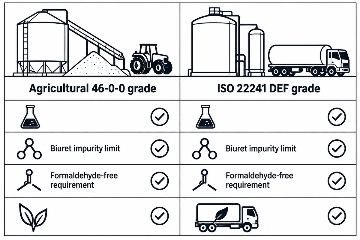
Roughly 90% of global urea produced each year goes to agricultural use on soil and crops to boost crop yields. Among commercial fertilizers used, it is the best solid fertilizer in agriculture and outperforms ammonium nitrate, calcium ammonium nitrate and ammonium sulfate, in terms of total nitrogen concentration. The remaining roughly 10% serves industrial applications including urea-formaldehyde resins, melamine, pharmaceutical intermediates, and automotive Diesel Exhaust Fluid (DEF / AUS 32, where an inline process refractometer verifies 32.5 wt% solution concentration). Urea is a highly soluble nitrogenous compound that offers concentrated plant nutrient nitrogen and blends well with monoammonium or diammonium phosphate (MAP/DAP). Purity specifications distinguish dry-solid and aqueous-solution mass bases. Agricultural 46-0-0 identifies the fertilizer’s nutrient grade, whereas ISO 22241-1 limits biuret to ≤0.3 wt% in finished 32.5 wt% aqueous AUS 32 solution.
A critical procurement mistake highlighted in ISO 22241-1:2019 technical compliance guidance for AUS 32 / DEF is dissolving standard agricultural 46-0-0 granules in water to manufacture SCR emission fluid. During fluidized-bed granulation, urea solution is conditioned with 0.2–0.5 wt% urea-formaldehyde additive. Under ISO 22241-1:2019, finished 32.5 wt% (31.8–33.2 wt%) aqueous DEF solution must contain ≤5 mg/kg (5 ppm) aldehydes and ≤0.3 wt% biuret. Trace metals (Ca, Fe, Cu, Zn, Cr, Ni, Al, Mg, Na, K) must stay within ≤0.2–0.5 mg/kg per element. Agricultural-grade urea can introduce contaminants and metals into DEF that impair SCR system performance. In addition, formaldehyde-conditioned granules can cause the finished 32.5 wt% urea solution to exceed the ISO 22241-1 aldehyde limit of 5 mg/kg. Automotive-grade urea must come from unconditioned melt or dedicated formaldehyde-free technical prills.
| Specification Parameter | Agricultural Prilled 46-0-0 (Dry Solid Basis) | Agricultural Granular 46-0-0 (Dry Solid Basis) | ISO 22241-1 AUS 32 / DEF (32.5 wt% Solution Basis) |
|---|---|---|---|
| Primary end-use market | Direct soil application, fertigation, foliar spray | Bulk mechanical NPK blending (with MAP/DAP) | Diesel SCR NOx reduction (automotive/marine) |
| Total nitrogen / urea content | ≥46.0 wt% N (dry solid fertilizer basis) | ≥46.0 wt% N (dry solid fertilizer basis) | 31.8–33.2 wt% urea (32.5 wt% target in demineralized H2O) |
| Maximum biuret content (note mass basis) | Set by buyer contract and crop application (low-biuret grades specified for sensitive foliar use) | Set by buyer contract and regional fertilizer standard on a dry solid basis | ≤0.3 wt% on finished 32.5 wt% solution basis |
| Formaldehyde / aldehyde conditioning | 0.0–0.3 wt% UF conditioner (unconditioned for DEF/resin) | 0.2–0.5 wt% urea-formaldehyde conditioning additive | ≤5 mg/kg aldehydes in the finished solution. |
| Moisture / water content | ≤0.3–0.5 wt% H2O | ≤0.2–0.4 wt% H2O | ~67.5 wt% ultrapure demineralized water |
| Dominant particle diameter | 1.5–2.2 mm (~1.65 mm mean in lab study) | 2.0–4.0 mm (2.82–3.06 mm dominant in lab study) | Aqueous liquid solution (32.5 wt% urea in demineralized water) |
| Particle crushing strength | 3.80 N (~0.39 kgf) lab sample; 0.8–1.5 kgf commercial | 10–17 N (~1.02–1.73 kgf) lab sample; 2.5–4.0 kgf commercial | Not applicable (liquid solution; freezes at −11 °C) |
| True crystal vs. loose bulk density | 1.32 g/cm3 crystal; 0.72–0.78 g/cm3 bulk | 1.32 g/cm3 crystal; 0.72–0.78 g/cm3 bulk | Aqueous solution monitored via inline refractometer |
| Trace metals (Ca, Fe, Cu, Zn, Cr, Ni, Na, K) | Governed by destination market fertilizer contaminant regulations and buyer purchase specifications | Governed by destination market fertilizer contaminant regulations and buyer purchase specifications | ≤0.2 to ≤0.5 mg/kg per element; insolubles ≤20 mg/kg |
Global Supply, Utility Consumption Benchmarks, and Green Urea Outlook
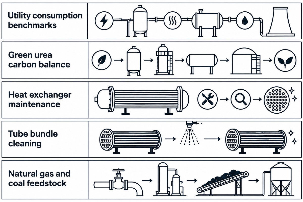
The global supply of urea, the most concentrated solid nitrogenous fertilizer in modern agriculture, tracks natural gas and coal feedstock availability. According to USGS nitrogen statistics and the USDA FAS fertilizer report, China, India, Russia and the Middle East account for the lion’s share of the nitrogen and urea production. In the U.S., fertilizer comprises 36% of corn operating costs and 35% of wheat operating costs. U.S. urea supply combines domestic production with seaborne and land-based imports from Qatar, Algeria, Russia, Canada, and Nigeria. New Orleans (NOLA) is a key Gulf import gateway. Facilities subject to U.S. EPA 40 CFR Part 98 follow its greenhouse-gas reporting requirements.
When considering plant revamps, blue/green urea retrofits, or heat exchanger replacements, engineers assess feedstock and utility consumption per metric ton of urea separately from spot fertilizer prices.
- Liquid ammonia (NH3) feedstock: 567 kg/t stoichiometric minimum; 570–580 kg/t (0.57–0.58 t/t) in commercial stripping plants.
- Gaseous carbon dioxide (CO2) feedstock: 733 kg/t stoichiometric minimum; 740–750 kg/t (0.74–0.75 t/t) in commercial plants.
- Steam consumption (20–25 bar HP stripper + LP recovery): 750–950 kg/t urea, with 350–450 kg/t of 4.5–5.5 bar low-pressure steam cogenerated in the high-pressure carbamate condenser.
- Electrical power consumption: 20–35 kWh/t in gravity/ejector CO2 stripping plants with turbine-driven CO2 compressors, or 85–115 kWh/t with electric motor drives and fluid-bed granulation blowers.
- Green urea carbon constraint: Replacing natural-gas reforming with renewable water electrolysis eliminates captive CO2 generation. Every 1,000 MTPD green urea train must secure 740–750 tonnes per day of purified biogenic or captured CO2.
Engineering RFQ Checklist for Urea Plant Heat Exchangers, Condensers, and Bundle Maintenance
- Loop architecture and operating envelope: State whether the synthesis loop uses CO2 stripping (140–145 bar, 180–185 °C, N/C ≈ 3.0) or NH3 self-stripping (150–155 bar, 185–210 °C, N/C = 3.3–3.6).
- Austenitic and duplex qualification: Specify low-ferrite UNS S31603 (316L UG with ASTM A262 Practice C ≤0.60 mm/yr intergranular screening per UreaKnowHow). For higher-duty strippers, select UNS S31050 (25Cr-22Ni-2Mo), super-duplex Safurex, or bimetallic Zr/Ti tubes. Heat Exchanger World cites API Std. 660 for a minimum 1.5 mm depth of undiluted corrosion-resistant alloy in tubesheet weld-overlay cladding; the finished overlay specification also defines the required alloy chemistry at the process-wetted surface.
- Passivation oxygen and liquid divider design: In the Brouwer / UreaKnowHow tests, 316L UG stayed passive at 5–7.3 ppm dissolved O2, while 25-22-2 stayed passive at 3 ppm O2. Specify tangential or ceramic falling-film liquid dividers for uniform tube wetting.
- Turnaround bundle extraction and hydroblasting: Check pull-space clearance for MP/LP decomposers, vacuum evaporators, and hydrolyzer exchangers. Match automated hydroblasting pressure (systems rated up to 40,000 PSI) to tube metallurgy and wall thickness with BOSHIYA’s petrochemical and chemical process equipment team.
Industrial Urea Production Frequently Asked Questions
What is the production of urea and how are urea fertilizers made?
Industrial urea fertilizer is made by reacting ammonia with carbon dioxide via the two-step Bosch-Meiser process at 180–200 °C and 140–250 atm. Anhydrous liquid ammonia and compressed CO2 first form ammonium carbamate, which partially dehydrates into urea and water. Stripping and downstream recovery then remove unconverted ammonia and carbamate to produce a 70–77 wt% aqueous urea solution. After stripping and recycling unconverted gases, vacuum evaporators concentrate the melt for prilling or granulation into solid 46-0-0 fertilizer.
Who is the largest producer of urea in the world, and where does the US get most of its urea from?
China, India, Russia, and the Middle East represent the largest global urea-producing regions tracked in USGS and USDA FAS nitrogen supply reports. United States urea supply combines domestic plant production with seaborne and overland imports from Qatar, Algeria, Russia, Canada, and Nigeria. New Orleans (NOLA) serves as a primary Gulf import gateway for bulk fertilizer shipments.
How much does 1 ton of urea cost to produce and buy?
Producing 1 metric ton of solid urea requires 570–580 kg of liquid ammonia, 740–750 kg of carbon dioxide, and 750–950 kg of steam. Bulk purchase prices follow spot FOB U.S. Gulf (NOLA) or Middle East market indices rather than a fixed dollar schedule. Cash production costs reflect feedstock, energy, and operating expenses, while seasonal planting demand influences market prices; public federal summaries don’t fix a single dollar cost per ton across facilities.
What is the density of urea?
Pure crystalline solid urea has a true density of 1.32 g/cm3, whereas commercial bulk prilled and granular urea fertilizers have a loose bulk density of 0.72–0.78 g/cm3 (720–780 kg/m3).
Why can’t standard agricultural urea granules be diluted directly to make Diesel Exhaust Fluid (DEF)?
Agricultural-grade urea can introduce contaminants and metals into DEF. Formaldehyde-conditioned granules (0.2–0.5 wt% urea-formaldehyde additive) can cause the finished 32.5 wt% urea solution to exceed the ISO 22241-1 aldehyde limit of 5 mg/kg, and contaminants can impair SCR system performance.
Specify Custom Heat Exchangers and Turnaround Bundle Cleaning for Fertilizer & Chemical Plants
BOSHIYA designs and manufactures ASME and TEMA shell-and-tube heat exchangers, process condensers, and PLC-controlled 40,000 PSI tube bundle cleaning systems. Manufacturing operates under ISO 9001 quality, ISO 14001 environmental, and ISO 45001 occupational health and safety management systems. Review our petrochemical and chemical plant equipment capabilities or contact our engineering team to discuss your urea and petrochemical heat exchanger requirements.
References & Sources
- AP-42 Chapter 8.2: Urea, Compilation of Air Pollutant Emission Factors U.S. Environmental Protection Agency (EPA).
- Briefing No. 112: Ammonia and Urea Production and Agricultural Fertilizer Markets Montana State University Agricultural Marketing Policy Center.
- HERO ID 2009046: Urea Formation from Carbon Dioxide and Ammonia U.S. Environmental Protection Agency Health & Environmental Research Online.
- Nitrogen Statistics and Information, Mineral Commodity Summaries U.S. Geological Survey (USGS) National Minerals Information Center.
- Impacts and Repercussions of Price Increases on the Global Fertilizer Market U.S. Department of Agriculture Foreign Agricultural Service (USDA FAS).
- 40 CFR Part 98, Mandatory Greenhouse Gas Reporting U.S. Environmental Protection Agency (eCFR, 2026).
- Urea Finishing Process: Prilling versus Granulation (Procedia Engineering, Rahmanian et al., 2015) White Rose University Consortium.
- High-Pressure Stripper Equipment Specification for Urea Stripping Plants Stamicarbon.
- Urea Synthesis with Pool Condenser and Vacuum Evaporation thyssenkrupp Uhde Fertilizer Technologies.
- Stainless Steels and Other Alloys in Urea Plants (Mark Brouwer) UreaKnowHow Technical Library.
- High-Pressure Urea Stripper Tubes Technical Datasheet Alleima (formerly Sandvik Materials Technology).
- High-Pressure Urea Stripper Tubing and Super-Duplex Safurex Development Heat Exchanger World.
- Cladding Applications in Shell-and-Tube Heat Exchangers (API Std. 660) Heat Exchanger World.
- Urea Production from Ammonia via a Self-Stripping Process Chemical Engineering Magazine.
- Differences Between Prilling and Granulation: Droplet Solidification Mechanics Kreber.
- ISO 22241-1:2019 Technical Specification Guide for AUS 32 / Diesel Exhaust Fluid Anytime Fuel Pros / ISO 22241 Reference.
- Urea Market Size, Share & Industry Analysis (2026–2034) Fortune Business Insights.
- WO2025155218A1, Process and Plant for Producing Urea WIPO / Google Patents, 2025.
- WO2025206949A1, Urea Stripping Process with Ceramic Liquid Divider WIPO / Google Patents, 2025.
- US20120302789A1, Urea Stripping Process USPTO / Google Patents.