Get in Touch with BOSHIYA


Updated August 2026
Contents
show
A U tube heat exchanger is a single-tubesheet, return-bend arrangement that handles differential tube growth. That mechanical benefit is useful only when the service also tolerates limited straight-through tube access, difficult inner-tube replacement, and the space and planning needed to remove the bundle.
Direct answer: Choose U-tube geometry for its thermal-growth freedom only after the fouling, inspection, repair, containment, and bundle-handling plan has been tested against the installed site.
Selection snapshot
| Tube termination | Both ends return to one tubesheet |
|---|---|
| Return path | A 180-degree U-bend |
| Primary design value | Lower restraint on differential tube growth |
| Primary access limit | No straight mechanical path through the return bend |
| Turnaround condition | A verified extraction and support envelope |
- Thermal-expansion accommodation isn’t the same as higher thermal efficiency.
- A removable bundle improves shell-side access; it doesn’t make every tube interior easy to brush.
- No public authority source supports one universal plugged-tube percentage.
- The pull lane, support plan, and changing center of gravity can matter as much as bundle mass.
What Changes in a U-Tube Exchanger?
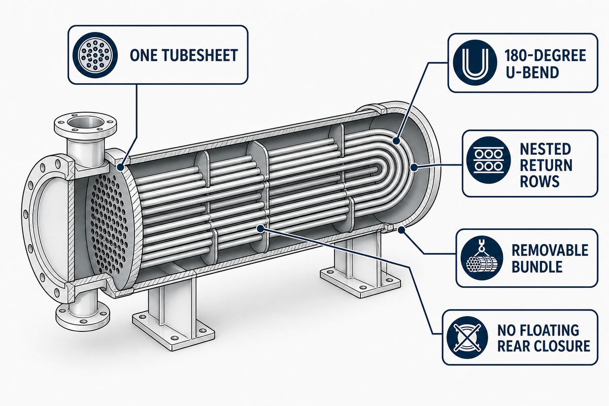
U-tube exchanger flow runs from the channel through a bank of tubes, around the return bends, and back to the same channel end. Both tube ends therefore terminate at one tubesheet, while shell-side fluid crosses the outside of the bundle.
Readers who need the full family overview can use BOSHIYA’s shell-and-tube heat exchanger fundamentals. This guide stays on the narrower decision: what the return bend changes for stress, fouling, inspection, repair, and turnaround access.
As a type of heat exchanger, the U-tube shell is a transfer device that keeps two fluids separated by tube walls while fluid flow carries energy between hot and cold streams. Whether the service is gas or liquid, the tube sheet, heat exchanger tube geometry, and adjacent tube spacing affect how the unit can transfer heat and later be inspected.
Even a u tube heat exchanger diagram can show only nominal geometry. Practical maintainability still depends on the as-built piping, supports, tool path, handling route, and inspection method.
| Geometry feature | Mechanical effect | Buyer question |
|---|---|---|
| One tubesheet | Both tube ends share the channel end | Can piping and channel work be cleared from that end? |
| U-bend | Tube length can change with less end restraint | Does the service create meaningful differential growth? |
| Nested return rows | Inner bends are harder to reach and replace | What inspection and repair tools must pass the bend? |
| Removable bundle | Tube exteriors and baffles can become accessible | Is a full extraction lane and support plan available? |
| No floating rear closure | Fewer rear-head parts, different repair options | Does reduced closure complexity outweigh retubing limits? |
Why the U-Bend Handles Differential Thermal Growth
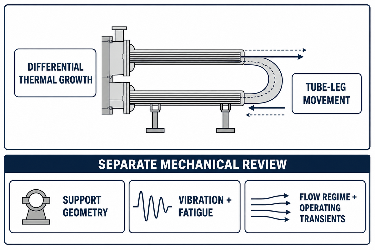
For services where shell and tubes don’t grow by the same amount, the return bend lets the tube legs change length without fixing both ends to opposing tubesheets. Geometry reduces one restraint mechanism; it doesn’t remove the need to calculate tubesheet loads, support behavior, vibration, or fatigue.
Heat exchanger design must treat expansion and contraction, thermal stress, and support loads together. High-temperature service or significant temperature variations may make free movement valuable, but thermally flexible geometry still needs dynamic checks; specialized steam generators in nuclear power plants illustrate why U-bend support and vibration can’t be ignored.
Published in 2022, an ASME Journal of Pressure Vessel Technology paper treats fixed, floating-head, and U-tube tubesheets as coupled mechanical systems. Its analysis is a useful warning against turning “free expansion” into a one-line sizing rule.
📐 Engineering boundary
A 2025 ASME PVP paper by Austin Vulcano, Gregory Banyay, Robert Blevins, and Pascal Brocheny reports vibration and accelerated wear in U-bend steam-generator tubes under specific high-flow, two-phase transverse conditions. That service-specific counterexample doesn’t cancel the thermal-growth benefit; it shows why support geometry and dynamic loads still belong in the mechanical review.
Buyers should therefore ask two different questions. First, does differential thermal growth justify U-tube geometry? Second, do the flow regime, supports, tube frequencies, and operating transients create a separate dynamic risk that the thermal-expansion answer can’t resolve?
U-Tube vs Fixed Tubesheet vs Floating Head
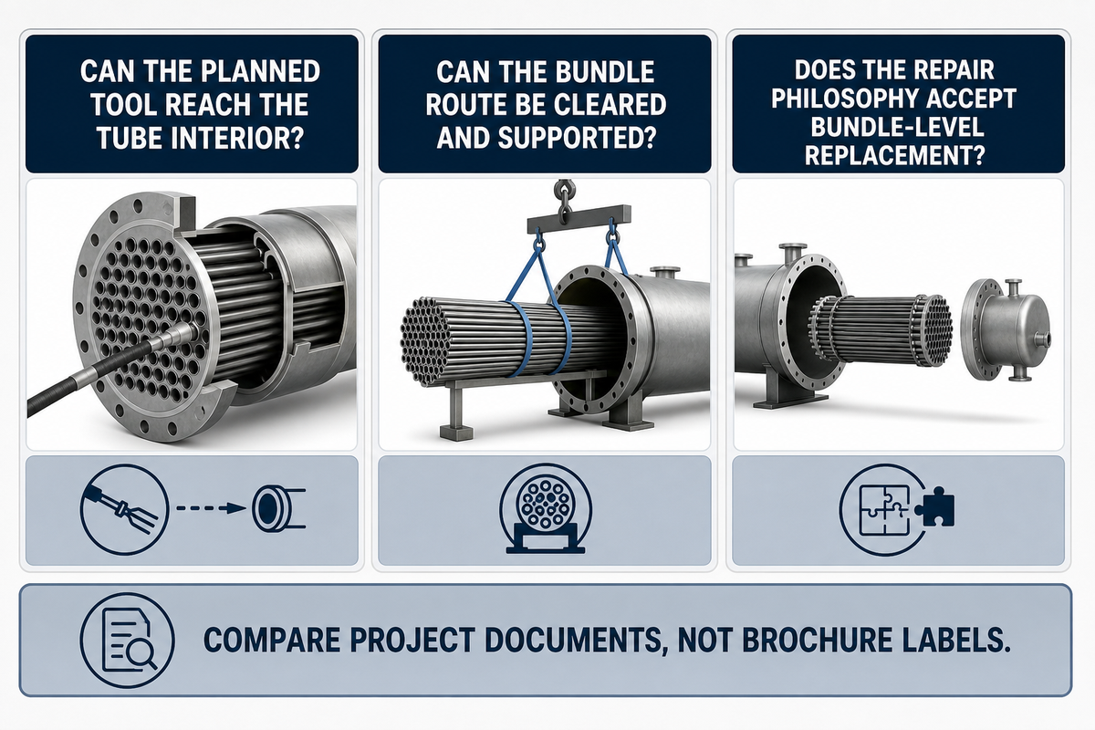
U-tube, fixed-tubesheet, and floating-head exchangers solve different combinations of thermal growth and maintenance access. Selection follows the dirtiest stream, cleaning tool, repair philosophy, containment duty, extraction route, and project requirements, not an unqualified ranking of cost or efficiency.
3-Door Maintainability Screen
This guide’s 3-Door Maintainability Screen is an evidence-driven worksheet. It isn’t a TEMA or ASME method and hasn’t been validated as a reliability predictor.
Claims that “u-tube heat exchangers offer unique advantages,” “good thermal performance,” or an “efficient solution” aren’t selection evidence. The supposed advantages of u-tube heat exchangers must be separated from service-specific limitations. Heat transfer efficiency, countercurrent behavior, heat transfer performance, and other heat exchanger features must be demonstrated for the actual duty instead of being inferred from a unique design label.
| Decision condition | U-tube | Fixed tubesheet | Floating head | Limitation / not suitable for |
|---|---|---|---|---|
| Differential tube growth | Return bend permits tube-leg movement | Needs a verified stress solution | Rear head permits movement | No geometry removes the need for mechanical analysis |
| Tube-side straight cleaning | Return bend limits straight tools | Straight-through access from channel ends | Straight tubes after head access | U-tube is a caution when rigid tools must pass through |
| Shell-side mechanical access | Bundle can be removed if installation permits | Bundle remains fixed to shell | Bundle removal is available | Removal still needs a lane, support, and lifting plan |
| Individual retubing | Nested inner tubes can be difficult to replace | Straight tube work is more accessible | Straight bundle supports retubing access | Confirm the repair philosophy before award |
| Internal rear closure | No floating rear-head joint | No removable rear closure | Additional closure and sealing details | Containment-sensitive service needs project review |
| Tube-side solids or hard scale | Bends can restrict cleaning access | Straight access may suit mechanical cleaning | Straight bundle supports mechanical access | Cleaning chemistry and tools must be proven for the deposit |
| Shell-side fouling | External tube surfaces become accessible after removal | Mechanical shell-side access is restricted | Bundle removal supports external cleaning | Tube pitch and deposit type still control access |
| Pull-lane availability | Full bundle route required | No bundle pull, but shell-side access remains limited | Full bundle route required | A removable design can be unmaintainable in a blocked layout |
| Buyer evidence | Cleaning, inspection, and extraction plan | Stress solution and shell-side maintenance plan | Closure, sealing, handling, and inspection plan | Compare project documents, not brochure labels |
The Cleanability Constraint Buyers Miss
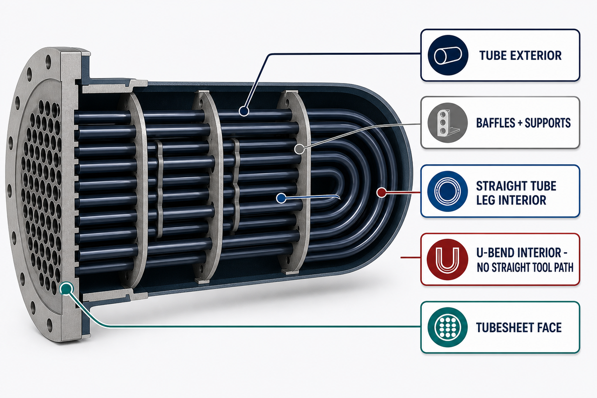
Bundle removal makes U-tube exteriors, baffles, and the shell side easier to reach after extraction. Tube interiors present a different access problem: rigid straight-through tools can’t pass a 180-degree bend, and deposits at the return can require flexible, chemical, or service-specific cleaning methods.
“Plot space: double the space needed for cleaning (i.e. to pull out the bundle).”
| Surface | Access after bundle removal | Decision before purchase |
|---|---|---|
| Tube exterior | Visible between accessible rows | Match tube pitch and deposit to the cleaning tool |
| Baffles and supports | Available for inspection where geometry permits | Define acceptance and repair evidence |
| Straight tube leg interior | Partial access from channel end | Confirm tool reach and retrieval |
| U-bend interior | No straight tool path | Prove flexible or chemical method for the deposit |
| Tubesheet face | Accessible after channel work | Include joint inspection and leak evidence |
An open-access 2021 ACS Omega paper reports a modeling-and-experiment setup with straight and U-shaped tubes under specific accelerated calcium-carbonate conditions: 1,000 mg/L hardness, 0.4 m/s flow, a 50 °C tank, and a 20 cm U-bend radius. Its useful lesson isn’t a universal cleaning recipe; it’s that local velocity, pressure, water chemistry, geometry, and mitigation method change the fouling result.
Maintenance and cleaning also depend on tube materials, corrosion-resistant requirements, deposit chemistry, and the expected tube failure mode. Common applications don’t create one U-tube applications rule: high pressure, a specific Section VIII construction basis, or an accessible shell side can matter, but none automatically makes a fouling service suitable.
U tube heat exchanger cleaning plans should name the deposit, method, bend reach, metallurgy check, waste path, and post-clean inspection evidence. A cleaning vendor’s method statement is more useful than a generic promise that the bundle is removable.
Do
- Name the fouling stream and deposit.
- Confirm the tool can reach and return.
- Define the post-clean inspection evidence.
Don’t
- Use removable as a synonym for fully cleanable.
- Assume chemical cleaning fits every metallurgy.
- Leave U-bend access for the outage team to discover.
Inspection and Repair Boundaries
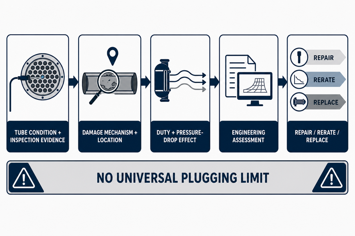
Inspection evidence should drive a U-tube repair decision, not an internet percentage. Tube condition, lost duty, pressure drop, leakage path, vibration, damage mechanism, applicable construction record, jurisdiction, and the approved repair method all affect whether plugging, rerating, repair, or bundle replacement is acceptable.
ASME’s public PCC-2 (2022) scope covers repair methods for in-service pressure equipment after appropriate inspection and flaw assessment. It also says inspection and flaw-evaluation methods live in other post-construction requirements, which is why this article doesn’t prescribe a universal plugging limit.
- Freeze the baseline — collect original data reports, drawings, applicable editions, duty cases, and prior repairs.
- Map the findings — identify tube location, depth, orientation, leakage evidence, fouling, and support condition.
- Recalculate the consequence — review duty, pressure drop, vibration, bypass, and containment effects.
- Choose the disposition — document why plugging, repair, rerating, or bundle replacement is accepted.
- Close the record — retain inspection results, calculations, approvals, test evidence, and as-left status.
How do you know a heat exchanger is bad?
Falling thermal approach, rising pressure drop, cross-contamination, unstable temperatures, leakage, abnormal vibration, or repeated cleaning demand can trigger inspection, but none proves the damage mechanism alone. Compare operating data with the clean baseline, then select examination methods that can reach the suspected location and resolve the expected flaw orientation.
What percentage of tubes can be plugged in a heat exchanger?
No percentage is universally safe. Acceptable results depend on how the plugged locations change heat-transfer area, velocity, pressure drop, vibration, bypass, and operating margin, as well as the governing jurisdiction and repair procedure. Ask the responsible engineer to document the calculation and the condition that would force rerating or replacement.
Where U-Tube Geometry Fits, and Where It Does Not
U-tube geometry fits when differential thermal growth matters, the tube-side fluid is compatible with the planned cleaning and inspection methods, shell-side bundle access has value, and bundle-level replacement is acceptable. It’s a poor default when straight-through cleaning or repeated individual retubing is central to the maintenance strategy.
| Service condition | U-tube response | Buyer action | Limitation / not suitable for |
|---|---|---|---|
| Meaningful shell-to-tube temperature difference | Return bend reduces end restraint | Verify the complete stress and support model | Do not infer better efficiency |
| Relatively clean tube-side service | Bend-access penalty may be manageable | Prove the cleaning and inspection method | Not a blanket clean-service label |
| Hard tube-side scale | Return bend becomes a cleaning constraint | Test flexible/chemical method or change geometry | Avoid unsupported brush-through assumptions |
| Shell-side fouling | Removable bundle can expose external surfaces | Confirm pitch, lane, and support access | Dense rows can still restrict cleaning |
| Rigid straight inspection tool required | U-bend may block the method | Validate tool reach before selection | Choose straight tubes if the method is mandatory |
| Expected individual retubing | Nested inner tubes can be difficult to replace | Compare bundle-level replacement economics | Do not rely on seller “easy replacement” copy |
| High-flow two-phase crossflow near bends | Dynamic wear may become load-bearing | Require vibration/support substantiation | ASME PVP result is steam-generator-specific |
| Contamination-sensitive duty | Joint and leakage consequences can dominate | Add project containment and monitoring review | No generic hygienic approval is implied |
| No usable extraction route | Removability exists only on the drawing | Change layout, handling plan, or configuration | Do not defer access to the turnaround |
| Service category | Evidence to request | Decision consequence |
|---|---|---|
| Configuration | Tubesheet, rear-head, pass, and bundle drawings | Confirms the actual access geometry |
| Thermal growth | Design cases and mechanical calculation | Tests whether the U-bend benefit is load-bearing |
| Tube-side cleaning | Deposit, tool, bend reach, and chemistry | Can disqualify U-tube geometry |
| Shell-side cleaning | Pitch, baffle access, and extraction route | Determines value of bundle removal |
| Inspection | Method, coverage, probe reach, and flaw orientation | Prevents an uninspectable inner row |
| Repair | Plugging, retubing, rerating, and replacement approvals | Exposes bundle-level replacement assumptions |
| Dynamic reliability | Support, vibration, transient, and wear assessment | Bounds thermal-expansion benefits |
| Containment | Joint, leakage, monitoring, and contamination review | Controls sensitive-service suitability |
| Bundle handling | Mass, dimensions, route, support, and uncertainty | Determines practical removability |
Bundle-Removal Readiness Before the Turnaround
Bundle-removal readiness exists only when geometry, mass, path, support, ground or structure capacity, pulling interface, and uncertainty are documented. Capacity labels can’t compensate for blocked piping, an unstable support condition, or an extraction lane shorter than the handling sequence requires.
7-Field Turnaround Envelope
This guide’s 7-Field Turnaround Envelope organizes planning evidence. It doesn’t replace a lifting plan, risk assessment, manufacturer procedure, or engineering approval.
| Field | Illustrative entry | Evidence owner | Release condition |
|---|---|---|---|
| Verified bundle mass | 18,000 kg example | Mechanical engineering | Drawing/calculation reconciled to as-built changes |
| Overall bundle length | 7.2 m example | Vendor + site survey | Handling length and attachments included |
| Maximum handling diameter | 1.4 m example | Vendor drawing | Flange, baffles, and temporary hardware checked |
| Centerline and approach | 2.1 m above grade example | Site survey | Equipment can align without pipe-rack conflict |
| Clear pull/push lane | 9.0 m example | Turnaround planning | Travel, staging, and reinstallation sequence fits |
| Support and bearing plan | Numeric capacity pending | Civil/structural engineering | Reaction loads and travel route approved |
| Breakout-force uncertainty | No assumed multiplier | Maintenance + equipment provider | Contingency tied to condition and pulling interface |
Third-party patent US6685423B1 describes how the bundle’s changing position can shift an extractor’s center of gravity and load distribution. US6685423B1 isn’t owned by BOSHIYA and doesn’t prove any BOSHIYA product capability; it’s useful only because it exposes stability and support as planning variables.
What U-Tube Installation Data Must Be Verified Before Bundle Removal?
Verify mass, length, diameter, centerline, pull and push path, overhead and side obstructions, piping removal, support reactions, ground or structure limits, pulling interface, staging route, reinstallation sequence, and the uncertainty created by deposits or corrosion. Then match those inputs to an approved handling and risk plan.
For a complete extraction and reinsertion sequence, use BOSHIYA’s bundle extractor procedure guide; this section only defines the U-tube installation’s clearance and handoff envelope. BOSHIYA’s public bundle puller selection tools include a bundle-weight calculator, extraction-force calculator, and capacity selector. Those are first-party commercial tools; they should be checked against project drawings, site conditions, and engineering approval rather than presented as independent industry standards.
RFQ Fields That Prevent a Maintainability Surprise

Maintainability-aware RFQs make process duty, fouling, materials, access, inspection, repair, bundle handling, edition, jurisdiction, and document ownership visible before bids are compared. This worksheet is an editorial planning aid; it isn’t a code-prescribed form or a guarantee of project performance.
U tube heat exchanger sizing begins with the complete duty envelope, while a u tube heat exchanger hydrotest requirement belongs in the project test and documentation plan. Neither phrase supplies a design value by itself.
A floating head heat exchanger alternative should remain on the bid table when straight mechanical cleaning or individual retubing is load-bearing. Every shell and tube heat exchanger comparison should use the same duty, fouling, access, and lifecycle basis.
TEMA’s official page now promotes the 11th Edition and lists expanded inspection, installation-operation-maintenance, repairs/alterations, and selection content. Write the project-required edition into the RFQ and ask vendors to identify deviations; “latest TEMA” isn’t an auditable requirement.
Post-construction work has a second control layer. National Board guidance says NBIC Part 3 covers repair and alteration verification and documentation for in-service pressure equipment, but adoption is jurisdiction-dependent, so the RFQ and asset record should name the governing construction and post-construction requirements separately.
Normalize vendor units before comparison and use one project-defined unit system: for US procurement, use duty in kW, MW, or Btu/h; temperature in °C or °F; pressure in bar(g), MPa(g), or psi(g); mass flow in kg/h or lb/h; volumetric flow in m³/h or gpm; tube velocity in m/s or ft/s; fouling resistance in m²·K/W or h·ft²·°F/Btu; corrosion allowance in mm or in; mass in kg or lb; dimensions in mm, m, in, or ft; nozzle loads in kN or lbf; vibration in mm/s or in/s; inspection coverage in %; and test duration in min or h. Each value remains project-specific.
RFQ checklist — copy these into your quote request:
| Parameter | Recommended range | Why it matters | How to verify |
|---|---|---|---|
| Duty cases | List each project case in kW, MW, or Btu/h | Prevents unlike thermal bases | Process datasheet and vendor calculation |
| Design temperatures | State minimum/maximum in °C or °F for both sides | Controls differential growth and materials | Approved design basis |
| Design pressures | State each side in bar(g), MPa(g), or psi(g) | Controls pressure boundary and tubesheet review | Datasheet and code calculation |
| Fouling and cleaning | Name deposit, interval basis, tool, and chemistry | Tests U-bend access against the maintenance plan | Cleaning trial/procedure and material review |
| Inspection access | Name method, probe size, bend reach, and coverage | Prevents an uninspectable inner row | Demonstration and inspection plan |
| Bundle handling | Mass in kg or lb, length/diameter in m or ft, centerline and lane | Defines extraction and support envelope | Certified drawing and site survey |
| Repair philosophy | Define plugging, retubing, rerating, and replacement approvals | Exposes lifecycle assumptions | Engineering assessment and applicable repair requirements |
| Edition/jurisdiction | Name each required edition and authority | Separates construction, inspection, and repair obligations | Vendor deviation list and document register |
Procurement can send the thermal and mechanical fields to bidders, but maintenance, inspection/QA, civil/structural, and operations must own their parts of the evidence. Finance also has a role: it should compare the consequence of unavailable inspection, blocked extraction, or bundle-level replacement rather than relying on a purchase-price-only table.
Key takeaway
U-tube geometry is a maintainability decision: approve it only when thermal growth, fouling, inspection, repair, and the 7-field extraction envelope all point in the same direction.
Frequently Asked Questions
Q: What is a U-tube heat exchanger?
A U-tube heat exchanger returns both tube ends to one tubesheet, reducing end restraint during differential growth while limiting straight mechanical access through the bends.
A U-tube heat exchanger is a shell-and-tube unit in which each tube bends back and both ends terminate at one tubesheet. The bend lets the tubes expand and contract with less restraint from the shell. The bundle may be removed for access to its outside surfaces, but the curved tube interior creates cleaning, inspection, and individual-tube replacement limitations that must be evaluated before selection.
Q: Why choose a U-tube exchanger over a straight-tube design?
Choose U-tube geometry when differential growth matters and the service tolerates bend-related cleaning, inspection, and repair constraints better than the available straight-tube alternatives for the actual duty.
Choose the U-tube arrangement when differential thermal growth is important and the tube-side service is compatible with the available cleaning and inspection methods. A fixed straight-tube design can be simpler but needs a verified stress solution. A floating-head design offers straight-tube access and expansion flexibility with different closure details. The choice depends on fouling, repair strategy, containment, duty, vibration, and lifecycle access, not geometry alone.
Q: Can U-tubes be mechanically cleaned?
Cleaning is side-specific: bundle removal improves external access, but the 180-degree tube bend restricts straight mechanical tools and may require flexible or chemical methods for the actual deposit.
Removing the bundle exposes tube exteriors and baffles for shell-side cleaning, while straight portions of the tube interior may accept some tools. The return bends limit straight mechanical access and can trap deposits, so a U-tube design should not be selected on the assumption that every internal surface can be brushed like a straight tube. Confirm the cleaning method, deposit, inspection tool, metallurgy, and manufacturer procedure for the actual service.
Q: Is a U-tube bundle removable?
Usually, but practical removability depends on installed piping, supports, bundle mass and dimensions, extraction clearance, staging space, and an approved handling plan at the installed site.
Confirm piping removal, supports, extraction path, bundle mass, clearances, staging route, and the approved lifting or handling plan before treating a U-tube bundle as field-removable.
Q: What U-Tube Bundle Data Is Needed Before Equipment Handoff?
Start with verified U-tube bundle geometry, mass, centerline, support reactions, pull and push route, site alignment, ground limits, and condition-related breakout uncertainty for the installed exchanger.
Record bundle mass, overall length, maximum diameter, shell flange and support geometry, centerline elevation, available pull and push path, overhead restrictions, ground or structure limits, travel route, and the uncertainty caused by fouling or corrosion. State whether the equipment must only extract, or also support, transport, and reinsert the bundle. Then check attributed provider data against the site plan and engineering assessment.
Turn the article into a field-ready handoff
Bring the seven envelope fields, exchanger drawings, service condition, and planned cleaning method. BOSHIYA can then discuss a bundle-handling route against its published equipment options and calculators.
How This Guide Draws the Boundary
BOSHIYA publishes this U-tube heat exchanger guide to help process, mechanical, maintenance, inspection, and procurement teams frame better questions before purchase or turnaround work. All three named worksheets are editorial tools built from the cited public evidence; they aren’t ASME, TEMA, NBIC, or patented BOSHIYA methods, and every project still needs its own engineering and jurisdiction review.
Related Resources
- Heat exchanger bundle weight calculator — structure the mass input before equipment selection.
- Bundle extraction force calculator — explore condition-related pulling inputs.
- Bundle extractor capacity selector — compare attributed first-party capacity options.
- Heat exchanger bundle cleaning systems — review shell- and tube-side service options.
- ASME pressure-vessel fabrication guide — separate construction records from maintenance decisions.
References & Sources
- Heat Transfer Equipment — Northwestern University Process Design.
- The Unified Theory of Tubesheet Design, Part I — ASME Journal of Pressure Vessel Technology.
- TEMA Standards, 11th Edition overview — Tubular Exchanger Manufacturers Association.
- Heat Exchangers Energy Efficiency Compendium — IPIECA.
- PCC-2: Repair of Pressure Equipment and Piping — ASME.
- U-Bend Tube Fluid-Elastic Instability Study — ASME PVP 2025; record hosted by Penn State.
- Flow and Fouling in Straight and U-Shaped Heat-Exchange Tubes — ACS Omega via PubMed Central.
- National Board Inspection Code Overview — National Board of Boiler and Pressure Vessel Inspectors.
- TEMA Standards and Shell-and-Tube Exchanger Design — Heat Exchanger World.
- US6685423B1: Heat Exchanger Bundle Extraction Apparatus — Google Patents record.
![Polypropylene Resin: Grades, Types & Selection Guide [2026]](https://boshiya.com/wp-content/uploads/2026/05/0-150x150.webp)