Get in Touch with BOSHIYA

Electric Arc Furnace (EAF): Process, Types & Steelmaking Guide
What Is an Electric Arc Furnace (EAF)? Process, Types, and Steelmaking Applications
Contents
show
Quick Specs: What Is an Electric Arc Furnace?
An electric arc furnace ignites a metallic charge with a direct face-to-face electrical arc, with line current passing from graphite electrode corners through the charge material. Highly concentrated arcs reach temperatures far beyond any combustion fuel, making the EAF the premier choice for both high-volume scrap recycling and precision alloy making.
| Parameter | Typical Range | Notes |
|---|---|---|
| Furnace capacity | 1 – 420 t per heat | Foundry units from 1 t; Tokyo Steel (DC) runs 420 t |
| Arc temperature | ~3,000 °C (5,400 °F) | Arc itself; charge reaches 1,600–1,800 °C molten |
| Transformer power | 10 – 150+ MVA | Mid-sized plant: ~60 MVA; 400–900 V secondary |
| Heat duration (tap-to-tap) | 40 – 90 min | ~50 min for 80-t AC EAF; ~60–70 min for 90-t medium-power |
| Energy consumption | 400 – 500 kWh/tonne | Theoretical minimum: 300 kWh/t; advanced 280–400 kWh/t |
| Electrode type | UHP graphite | AC: 3 electrodes; DC: 1 electrode |
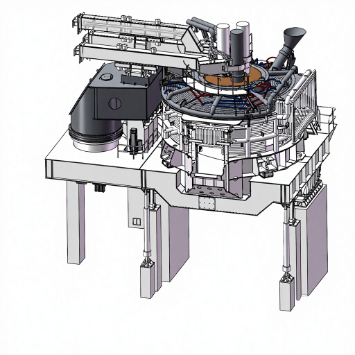
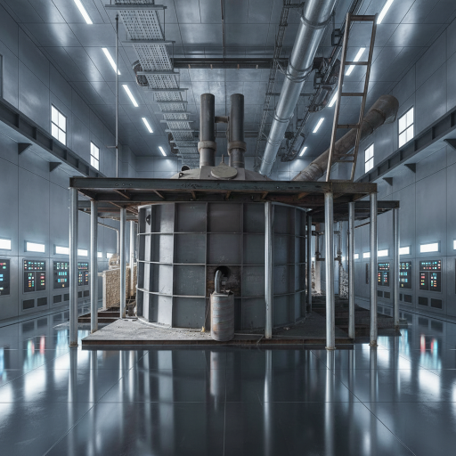
Three major structural sections define every EAF: the shell (sidewalls and lower steel bowl), the hearth (refractory-lined lower bowl holding molten metal), and the roof (retractable or swing-out, supporting graphite electrodes through a central delta). Modern plants often raise the furnace off-grade level so ladles and slag pots can be positioned directly beneath either end.
How Does an Electric Arc Furnace Work? Step-by-Step Process
Within a single EAF vessel, operators must accomplish tasks that integrated mills spread across multiple units: melt the scrap charge, achieve dephosphorization and decarburization, raise temperature, deoxidize, desulfurize, remove inclusions, and adjust both chemical composition and thermal conditions. That operational density makes EAF process control genuinely demanding. Mastering the EAF steelmaking process from cold charge to tapped heat is the foundation for sound plant investment and engineering decisions.
Scrap and Metal Feedstock: Preparing the Charge for EAFs
- Scrap Charging. Scrap steel is loaded into large baskets (“charge buckets”) layered strategically: heavy melt at the base, lighter shred on top for arc protection. With the roof swung open, the basket tips and cold scrap falls in. Charge operators consider this the highest-risk phase — thousands of kilograms of falling metal displace any retained liquid metal upward. A pre-heater may recover off-gas energy before the basket reaches the melt shop.
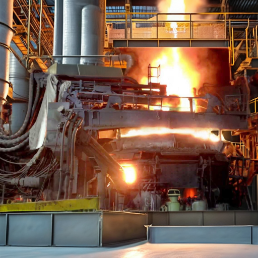
- Meltdown (Power-On). Electrodes lower onto the scrap; an arc is struck at reduced voltage to protect the roof. Once arcs bore into the heavy melt layer and are shielded by surrounding scrap, voltage increases and arc length extends — accelerating melt pool formation. Oxygen lances and sidewall oxy-fuel burners supply chemical heat to cold spots, particularly near the hearth perimeter in AC furnaces. Meltdown accounts for 60–70% of total electrical energy consumed per heat.
⚙ Engineering Note — Bore-In Voltage Management: After the charge has melted more than three-quarters, the arc is no longer shielded by solid scrap. Prolonged high-power input at this stage directly exposes the furnace roof and sidewalls to arc radiation. Operators reduce power at this transition point, but without real-time melt pool sensors, the timing relies heavily on operator experience — listening to furnace acoustics or watching light emissions from the slag door.
- Refining. Once the entire charge of scrap is in liquid form, additional slag—specifically calcined lime and dolomite mortar—are introduced to produce a basic slag layer. Injection of oxygen dephosphoryates and removes phosphorus, sulphur, silicon, aluminum, manganese, as well as additional carbon. Simultaneous injection of carbon into the slag releases CO gases which “foam” the slag, improving arc shielding, thermal efficiency, and electrical efficiency metrics. Should the temperature fall below roughly 1,530 C, the C–O combination begins to temporarily slow or stop, then reverse (“surge back”); this process produces violent slag overflow. Real-time sampling of temperature and chemistry occur using automated Lances; a “chill sample” is spectrometrically examined to verify grade.
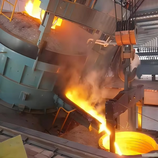
- Tapping. Once temperature and chemistry targets are met, the furnace tilts and liquid steel flows through an eccentric bottom tap-hole (EBT) into a pre-heated ladle. Alloy additions are made during tapping. A “hot heel” — a few tonnes of retained liquid steel and slag — is often left to preheat the next charge and accelerate its meltdown. From there, the ladle moves to a ladle furnace (LF) for secondary steelmaking — final chemistry and temperature adjustment — before continuous casting. Each heat of steel from charge to tap runs 60–90 minutes in a modern EAF.
⚡ Common Misconception: Many engineers assume EAF operations are as inflexible as blast furnaces, which run continuously for years at a time and cannot simply be “paused.” In reality, an EAF can be cold-started in under an hour and shut down just as quickly — a major operational advantage for plants adjusting to demand fluctuations or electricity pricing windows.
AC vs. DC Electric Arc Furnace — Types and Configurations
Two primary EAF configurations dominate modern steelmaking. A DC arc furnace uses a single graphite electrode and a conductive hearth return path; an AC design uses three electrodes fed by a three-phase supply. Understanding their differences allows project teams to select the right design for their production scale, power supply constraints, and scrap mix. For detailed steel plant configuration guidance, compare the key parameters below.
| Parameter | AC (Three-Phase) | DC (Single Electrode) |
|---|---|---|
| Electrodes | 3 graphite electrodes (three-phase supply) | 1 graphite electrode + conductive hearth return |
| Capacity range | Foundry units to 300+ t | 30 t to 420 t (Tokyo Steel) |
| Electrode consumption | Higher (3 electrodes in simultaneous use) | Lower per tonne (single electrode; less thermal cycling) |
| Power quality | Higher harmonic distortion; visible flicker on grid | Lower harmonics; less grid flicker |
| Hearth uniformity | Hot/cold spots between electrodes; burners compensate | More uniform melt bath stirring |
| Key limitation | More electrode breakage risk; hot spot refractory wear | Conductive hearth maintenance is a long-run bottleneck |
| Best suited for | Most mini-mills; any grid infrastructure | High-capacity, low-electrode-cost operations |
🔧 AC vs. DC Selection Framework:
- Capacity < 100 t and utility infrastructure is typical standard AC three-phase is the proven, lower-risk alternative
- Capacity > 100 t and electrode cost is a significant variable operating expense DC single-electrode requires less consumables
- Weak grid or power quality issue DC cuts flicker and harmonic distortion penalties
- Specialty ferroalloy or calcium carbide production Consider the use of a submerged arc furnace (SAF), a similar arc-heating setup with the submerged electrode tips, for unattended operation
DC Arc Furnace: Single-Electrode Configuration and Selection Logic
A DC arc furnace achieves uniform melt bath stirring with a single graphite cathode and a conductive bottom anode built into the hearth. This design reduces electrode consumption by 20–30% per tonne versus AC and cuts grid flicker — a meaningful advantage where grid tariffs penalize power quality disturbances. High-capacity DC arc furnaces up to 420 t (Tokyo Steel) dominate where electrode cost is the primary variable cost driver.
EAF Key Components — Electrodes, Shell, Refractory, and Furnace Design
EAF component integrity determines furnace productivity, safety, and consumable cost. For maintenance teams managing industrial maintenance equipment at steel plants, understanding the specification requirements of each component is essential for effective turnaround planning. Heat exchanger bundle cleaning and tube-side maintenance play a parallel role at the transformer cooling circuit — see heat exchanger bundle cleaning systems for steel plant applications.
Graphite and Carbon Electrodes: HP, SHP, and UHP Grade Guide
⚙ Engineering Note — Graphite Electrode Specifications:
- HP (High Power): 200-600 mm diameter and 15-25 A/cm current density resistivity 6.5 m
- SHP (Super High Power): 250-450 mm resistivity 5.8 m; bending strength 11 MPa
- UHP (Ultra High Power): 250-700 mm 30 A/cm current density resistivity 5.8 m ash 0.2%
- Standard lengths: 1,600-2,700 mm by diameter segments joined with threaded 4TPI nipples
- electrode consumption: around 1.2-3.0 kg per tonne of Liquid steel, varies with grade and process
- Estimated cost: $4.00-$7.00/kg (grades UHP to HP) – a significant process cost element
electrode grades correspond to transformer size: HP for foundry and ladle furnace use, UHP for high-capacity EAF steelmaking. Electrode segments are continuously added as upper segments wear away.
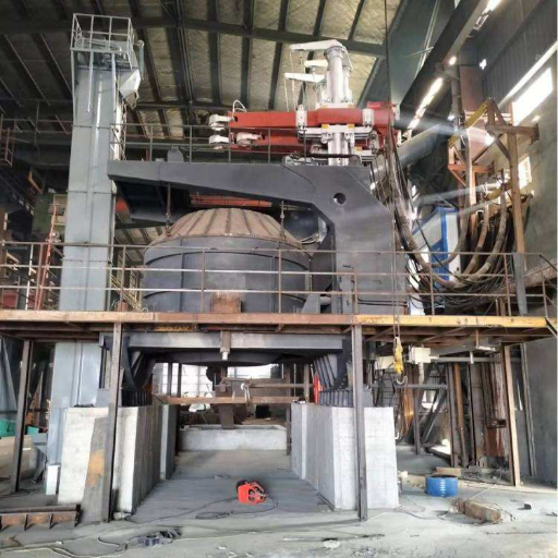
Furnace Shell, Furnace Bottom, Roof, and Refractory: Structural Systems
In addition to the electrodes, four other subsystems govern the effectiveness of EAF design:
- furnace shell: Water-cooled steel panels (top half) and refractory-lined lower cup. Any water contact with molten steel causes a steam explosion hazard due to panel leaks.
- Refractory lining (hearth): MgO-C or dolomite bricks up to 600 mm thick. Removed in time; refractory wear accelerates on sidewalls during high-voltage arcs that hit the surface before the scrap near them is melted through.
- Roof: Either refractory-lined or water-cooled. Supports the central refractory delta through which electrodes pass. Retractable or swing-off design for scrap charging access. Heat exchanger bundle pullers for steel applications address similar heavy-component extraction challenges during maintenance cycles.
- Furnace bottom (hearth): The refractory-lined base that contains the liquid metal pool. Regular bottom thickness monitoring — via thermocouple arrays — prevents breakout risk and determines reline scheduling.
- Off-gas and dust collection: EAF dust absorbs zinc, lead, manganese and hexavalent chrome—this is hazardous waste according to the EPA (40 CFR Part 63 Subpart YYYYY). US EPA estimates that about 130 EAF plants produce regulated slag and dust. Dust collection of funds—EAFs must not go without it; new EAFs have a huge capital investment.
Electric Arc Furnace vs. Blast Furnace (BF-BOF) — Direct Comparison
EAF and the blast furnace-basic oxygen furnace (BF-BOF) route represent genuinely different steelmaking philosophies, not just process variants. Both are primary steelmaking routes for producing liquid steel, but their economics diverge sharply: EAF’s low capital cost per tonne of installed capacity is a structural advantage, while BF-BOF’s strength lies in high-volume flat product at the upper end of the scale. Selecting between them — or managing a conversion from one to the other — requires a clear-eyed comparison across six dimensions. For EPC project services for steel plants, the technology choice drives every downstream specification decision.
| Dimension | EAF (Electric Arc Furnace) | BF-BOF (Integrated Mill) |
|---|---|---|
| Primary feedstock | Scrap steel + DRI/HBI/pig iron | Virgin iron ore + coking coal |
| Energy source | Electricity (400–500 kWh/t) | Coal/coke (~5,555 kWh equivalent/t) |
| CO₂ intensity | 0.6–0.7 t CO₂/t steel | 2.3–2.9 t CO₂/t steel |
| Capital cost | ~$140–200/t annual capacity (mini-mill) | ~$1,000/t annual capacity (integrated mill) |
| Operational flexibility | Cold-start in <1 hr; stop/start freely | Continuous; shutdown = weeks of lost production |
| Steel grade range | ~90% of grades; 100% with DRI addition | Full range including all ULC/electrical grades |
Can Electric Arc Furnaces Make Steel from Iron Ore?
Not directly. EAFs require a pre-reduced, metallic feedstock: scrap steel, direct reduced iron (DRI), or hot briquetted iron (HBI). Iron ore must first be reduced in a shaft furnace — using natural gas or hydrogen — to produce DRI before it can enter an EAF charge mix. This DRI-EAF hybrid route is currently the dominant pathway for green steel production, since replacing natural gas with hydrogen eliminates the process’s remaining CO₂ output.
📋 Project Scenario Matrix — Which Route Fits?
- scrap-based area + decarbonized grid EAF—lowest capex, lowest CO, workable immediately
- Emerging market + wealth of iron ore + cheap coal BF-BOF remains feasible—but risk of lock-in awaiting 2050 carbon pricing increase
- Green EAF using fresh DRI/H supply—Sustainable strategy; CBAM exempt; 95% of CO savings achievable
- Market commodity is best served by a greenfield mini-mill (of less than 300 T)—cheaper capex by 5-7 than integrated mill; more quick-to-market
Steel Grades Produced by EAF — From Carbon Steel to High Alloys

A misconception in steelmaking is that the EAF steel is a “lower-quality” product. It’s outmoded. Tata Steel UK reports that EAF process “already can [produce] 90 percent of the grades of steel that blast furnaces can – and the addition of a virgin iron source (DRI/HBI/pig iron) opens up the ability to make the most demanding of steel products.” So false-flag supply chains can produce the same quality of steel: Arvedi in Italy and Salzgitter in Germany (EAF) supply Mercedes-Benz; and Brookfield, Arcelor-Mittal’s EAF in Hamilton, Ontario, supplies General Motors with a product of 70 percent recycled content or more.
What actually determines grade capability is not furnace type but feedstock purity — specifically the ratio of virgin iron to scrap and the level of residual “tramp elements” (copper, tin, zinc) that cannot be removed from a scrap-based melt.
| Category | Grade Examples | EAF Feasibility | Key Requirement |
|---|---|---|---|
| Carbon steel | ASTM A36, A572 | ✅ Fully established | Standard scrap charge |
| Alloy steel | SAE 4140, 8620 | ✅ Fully established | Ferroalloy addition at tapping |
| Stainless steel | Grade 304, 316L | ✅ Standard route | LC-FeCr (Cr ≥ 60%, C ≤ 0.3%) + AOD/VOD refining |
| AHSS (automotive) | DP600–DP1000 | ✅ Expanding (U.S. Steel Big River) | High-purity scrap mix + precise alloy control |
| Tool steel | H13, D2 | ✅ Specialty EAFs | Small furnace + vacuum degassing |
| Ultra-low carbon / electrical steel | IF steel, silicon steel | ⚠️ Challenging | Higher N₂ absorption in EAF is detrimental; possible with vacuum treatment |
EAF Energy Consumption and Operating Cost — What to Expect
Electricity is the dominant variable operating cost in EAF steelmaking. Understanding what drives it — and how to reduce it — is central to plant economics. For full-plant cost modeling support, see Boshiya’s steel plant cost estimator and technical service and support.
400–500
kWh per tonne of steel
(industrial benchmark)
(industrial benchmark)
$35–60
Electricity cost per tonne
(at $0.10/kWh)
(at $0.10/kWh)
1.2–3.0
kg graphite electrode
consumed per tonne
consumed per tonne
8.9%
vs ~5,555 kWh/t for
BF-BOF (total energy)
BF-BOF (total energy)
Energy consumption varies significantly by configuration and operating practice. Modern EAFs with scrap preheating (Consteel process, shaft furnace) achieve 280–400 kWh/t — well below the conventional batch-charged range. Meltdown is the peak demand phase: a 50-tonne EAF may require 60–80 MW of instantaneous power during bore-in, tapering to 30–50% of rated capacity during the refining stage.
⚙ Energy Saving Lever — Foaming Slag Practice: Injecting carbon (coke fines or coal) into the liquid slag layer produces CO bubbles that “foam” the slag, raising its height to submerge the arc completely. Acting as insulation, this foam blanket absorbs and redirects arc radiation that would otherwise escape to the furnace walls and roof. This reduces direct heat loss from the arc, improves energy transfer to the melt, and extends refractory life. Effective foaming slag practice can meaningfully reduce heat losses and shorten power-on time per heat.
💡 Tip — Off-Peak Scheduling: Because EAFs draw large amounts of power in short bursts, many steel mills schedule heats to coincide with off-peak utility windows when grid electricity is cheapest. Starting and stopping within minutes, EAF is uniquely suited to this demand-response approach — a flexibility that blast furnaces simply cannot match.
EAF Slag: Volume, Composition, and Reuse Options
Each heat produces 80–150 kg of EAF slag per tonne of steel — a calcium-alumina-silicate material containing iron oxide and manganese. Unlike blast furnace slag, EAF slag chemistry varies with scrap feed and grade targets. Steel plant operators recover metallic iron from the slag through crushing and magnetic separation, then sell the processed material as road base aggregate or cement raw feed, reducing waste handling cost and supporting circular economy credentials.
EAF and Green Steelmaking — Trends Shaping the Industry Through 2026
Steel production accounts for 7–9% of global CO₂ emissions. EAF’s ability to process recycled materials at industrial scale — converting post-consumer scrap into new steel products — gives it a structural carbon advantage over virgin ore routes. That advantage has made EAF the de facto technology choice for the industry’s decarbonization transition, but the strategic landscape is moving faster than most engineers expect.
As of 2024, EAF represents 32% of global operating steelmaking capacity but an accelerating 49% of all new capacity under development — up from 33% in 2022 and 43% in 2023.
IEA’s Net-Zero Emissions scenario targets 37% EAF share by 2030, and current development pipelines put that target within reach for the first time. As the share of EAF production in global capacity continues to grow, investment in EAF technology — from advanced scrap preheating to hydrogen-DRI shaft furnace integration — is accelerating the industry’s decarbonization trajectory.
For steel and metal plant solutions tailored to decarbonization transitions, three EAF pathways now define the green steel roadmap:
📊 The Green Steel Carbon Math: How Grid Carbon Intensity Affects EAF’s Advantage
EAF’s 0.6–0.7 t CO₂/t advantage is calculated from electricity with an average grid intensity. But that advantage is not uniform globally:
- On a renewable grid (0.1 kg CO₂/kWh): EAF at 450 kWh/t = ~0.045 t CO₂/t — near zero
- On a US average grid (0.4 kg CO₂/kWh): EAF at 450 kWh/t = ~0.18 t CO₂/t — still 92% below BF-BOF
- On a coal-heavy grid (0.8 kg CO₂/kWh): EAF at 450 kWh/t = ~0.36 t CO₂/t — ~84% below BF-BOF, but the advantage narrows
Implication for project decisions: EAF’s carbon benefit scales with grid decarbonization. A steel plant in a renewable-power region captures far more decarbonization value than one on a coal-heavy grid — and that value will be enforced by the EU’s Carbon Border Adjustment Mechanism (CBAM), which phases in from January 2026.
Frequently Asked Questions — Electric Arc Furnace
What are electric arc furnaces used for?
EAFs melt scrap steel and DRI into liquid steel for casting. Beyond bulk carbon steel, they produce stainless steel, ferroalloys, calcium carbide, and specialty alloys. Foundry EAFs (1–10 t) cast components directly from molten metal — and processing 100% recycled scrap places them at the heart of steel’s circular economy.
How are electric arc furnaces powered?
AC EAFs are powered by a three-phase electrical supply fed through a dedicated transformer (10–150+ MVA). DC EAFs use a rectified DC supply to a single electrode plus a conductive hearth return path. Neither type requires fossil fuels for melting — the arc itself generates all the heat needed to reach 1,600–1,800°C. Supplementary oxy-fuel burners are sometimes used to pre-heat cold spots but represent a minor portion of total energy input.
How many electric arc furnaces are in the US?
Approximately 90–100 EAF-based steelmaking facilities operate across the US, where EAFs account for roughly 70% of total steel production — the highest EAF share of any major steelmaking nation. Globally, EAF represents around 30% of production. US industry’s heavy EAF reliance reflects its abundant scrap supply, relatively clean grid, and the mini-mill model pioneered by Nucor starting in 1969. EPA tracks approximately 130 facilities that generate regulated EAF slag.
Do electric arc furnaces use coal or coke?
EAFs do not use coal or coke as a primary energy source — that is the fundamental difference from blast furnace steelmaking. However, small amounts of carbon (coal fines or coke breeze) are typically injected into the slag layer during the refining phase for the foaming slag practice, which improves energy efficiency and arc stability. This carbon addition is measured in kilograms per tonne, not the thousands of kilograms of coking coal consumed by a blast furnace.
Can an electric arc furnace make steel directly from iron ore?
No. EAFs require a pre-reduced, metallic feedstock: scrap steel, direct reduced iron (DRI), or hot briquetted iron (HBI). Iron ore must first be chemically reduced in a shaft furnace — typically using natural gas, or hydrogen in green steel applications — to produce metallic DRI before it can enter an EAF charge mix. DRI-EAF combination is the leading pathway for producing primary steel with significantly reduced CO₂ emissions.
What are the main disadvantages of an electric arc furnace?
Four primary challenges face EAF operators: (1) Electricity cost sensitivity — energy is the largest variable cost, and grid prices directly determine margin competitiveness; electricity represents roughly 40–60% of variable OPEX in high-tariff markets; (2) Tramp element control — scrap contains residual copper, tin, and zinc that cannot be oxidized out, limiting high-specification grades unless premium scrap or DRI supplements the charge mix; (3) Lower throughput ceiling than large integrated BF-BOF mills for flat rolled product at the highest volumes; and (4) Grid flicker and power quality — large EAFs draw heavy, rapidly cycling loads that can affect surrounding grid users, requiring active power quality compensation equipment such as static VAR compensators.
Who invented the electric arc furnace?
Paul Héroult of France developed and commercialized the AC electric arc furnace for steelmaking, establishing the first commercial plant in the United States in 1907. Earlier roots trace to experiments by Vasily Petrov (1803) and Sir William Siemens (1878–79). In modern steel, Nucor pioneered the EAF mini-mill model in the US starting in 1969, transforming EAF from a specialty tool into the dominant steelmaking route in North America.
EAF Steelmaking: The Equipment Behind the Process
Understanding the EAF process is one step — keeping the plant running efficiently requires the right maintenance equipment for every component in the chain. Boshiya supplies specialized equipment for steel and metal plant operations, including transformer cooling circuit maintenance, heat exchanger service, and bundle extraction for steel plant heat transfer systems.
Whether your plant is evaluating EAF configuration options or maintaining an operating mini-mill, our team can help. Talk to a Steel Plant Equipment Specialist
![ASME Pressure Vessel Fabrication Guide: Section VIII Requirements [2025]](https://boshiya.com/wp-content/uploads/2026/05/2-46-150x150.webp)