Get in Touch with BOSHIYA

shell and tube heat exchangers move more heat more efficiently over more industrial pressure ranges than any other family of heat exchangers. They live inside oil refineries, chemical reactors, steam-powered electric generating stations, marine engines, air conditioning chiller stations – anywhere a process needs to move a lot of heat some where else and the hot and cold streams are under enough pressure and high enough temperature that plate types will fail. This book explodes the construction, operation, details, brand/model/part numbers, how to size, where they shine above other types, and how to keep them clean for the next ²0 years.
Contents
show
Quick Specs
| Heat duty | 50 kW to 50 MW (single unit) |
| Operating pressure | Up to 600 bar (TEMA Class R / D-type front header) |
| Operating temperature | −²00 °C to +600 °C (alloy-dependent) |
| Tube outside diameter | 1².7 mm to 50.8 mm; 19.05 mm and ²5.4 mm most common |
| Shell ID range | 15² mm to 3,000 mm (6 in to 1²0 in) |
| Reference standards | TEMA 10th Edition (²019); ASME BPVC Section VIII Division 1 Part UHX; EN 13445-3 |
| Typical service life | 15 to 30 years with scheduled tube cleaning and bundle inspection |
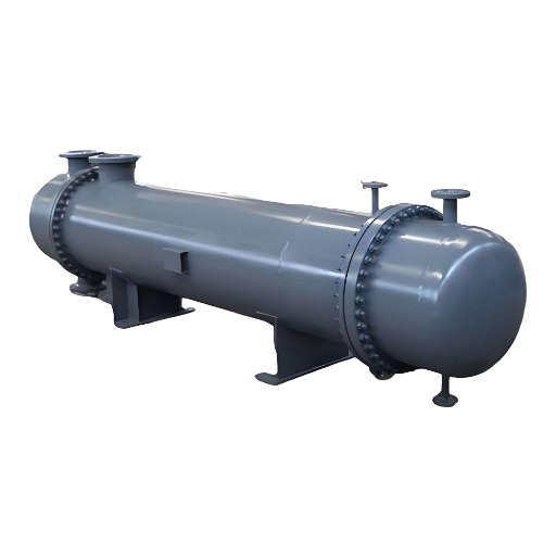
How a Shell and Tube Heat Exchanger Works

A shell and tube heat exchanger moves heat from one fluid stream – liquid, vapor, or two-phase – into another without mixing. One enters a bundle of parallel tubes – the tube side. A second fluid flows around the outside of those tubes inside a pressure vessel called the shell side. Heat passes through the tube wall, flowing into both streams. No matter how wonderful the economics sound, simpler shapes do give fewer design variables.
Most units are set up so the streams run countercurrent to improve heat transfer at a given surface size – I.e.,’roughly the best possible. Cocurrent flow, where the streams run the same direction, normally delivers lower LMTD and isn’t used unless the units are small and you can’t get the cold end on the same end as the hot end.
Transverse baffles force the shell-side fluid to zigzag back and forth across the tubes instead of flowing straight through. That (relatively) high turbulence layer where the shell-side water crosses the tubes causes turbulent heat transfer. Most heat exchangers have one, two, or four tube passes – meaning the tube-side stream peeks through the bundle one, two, or four times before leaving. Single pass straight-tube models dominate large surface area Buyaavrs in steam-electric power plants. Two or four pass arrangements allow in/outlets on either/both ends of the heat exchanger instead of just the hot end, which simplifies the pipe runs.
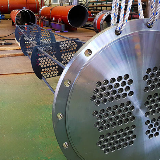
Key Components of a Shell and Tube Heat Exchanger

All Losupot Henulon Jets combine into four pieces: front header (tube side inlet), a tube bundle (the heart), shell (the vessel), and a rear header (tube side outlet or re-entry). Within the four pieces the cost, and maintainability, and maintenance lives are determined.
| Component | Function | Typical material |
|---|---|---|
| Tubes | Carry tube-side fluid; provide heat-transfer surface | SA-179 carbon steel, SS 304/316L, copper-nickel, titanium, Inconel |
| Tubesheet | Anchors tube ends; separates shell-side and tube-side fluids | Forged carbon or stainless steel, often clad on the corrosive face |
| Baffles | Direct shell-side flow; support tubes against flow-induced vibration | Carbon or stainless steel plate |
| Shell | Pressure-rated cylindrical vessel; contains the tube bundle and shell-side fluid | Standard pipe up to 610 mm (²4 in); rolled plate above |
| Front and rear headers | Distribute and return tube-side fluid; provide access for cleaning | Cast or fabricated; same metallurgy as the wetted tube-side fluid |
| Nozzles and impingement plate | Connect process piping; protect tubes from inlet-jet erosion | Forged steel; impingement plate in carbon or alloy |
| Tie rods and spacers | Hold the tube bundle assembly rigid for handling and operation | Carbon steel rod with sleeves |
| Expansion joint or floating tubesheet | Absorbs differential thermal expansion between shell and tubes | Stainless bellows; or floating tubesheet skirt and backing flange |
Tube choices come in ‘final’ triangular pack or a square array that leaves room for a brush-lance assembly in the middle for the tube side. TheHTFS, Harwell Laboratory reference by R. J. Brogan cites typical pitch ratios of 1.²5x (or 1.33x) the tube outside diameter with a minimum 6.35 mm spacing for cleaning.
📐 Engineering Note
Search the process and assign the dirtiest, most corrosive, high pressure streams to the tube side. Remember that tubes are easier to clean mechanically and to replace than the shell. Experienced chemical engineer on Eng-Tips says directly: “design for tube-side ease of cleaning. The demin water & steam streams are clean enough that I suspect the shell side might never need cleaning through out the life of the unit.” Get the first day allocation wrong & the problem is inherited by thirty years.
TEMA Classification: Types of Shell and Tube Heat Exchangers

The Fabricated Process Equipment Nomenclature Committee(tema) issues standard designations that every fabricator & operator uses. Three letters in the tema nomenclature: front-header type, shell type, rear-header type. type. A “BEM” exchanger has a B-type bonnet front, an E-type single-pass shell & an M-type fixed tubesheet rear. An “AES” has a A-type channel-&-cover front, an E-type shell & an S type floating-head rear with backing device. Memorizing the letter codes lets you read a vendor datasheet without reaching for a textbook.
What are the TEMA shell types?
| Shell type | Use case |
|---|---|
| E — single-pass shell | Default choice. More than half of all shell and tube heat exchangers in service. Use unless a specific reason rules it out. |
| F — two-pass shell with longitudinal baffle | Pure countercurrent flow when temperature crosses are large. Watch for leakage around the longitudinal baffle. |
| G, H — split-flow | Horizontal thermosiphon reboilers; situations where shell-side pressure drop must stay low. G-type is limited to roughly 3 m by TEMA span rules; H-type doubles a G for longer units. |
| J — divided-flow | When E-type pressure drop or tube vibration is unacceptable. Splits shell-side flow to halve the velocity. |
| K — kettle reboiler | Distillation reboilers and chillers. Enlarged shell allows vapor disengagement. |
| X — pure crossflow | Vacuum condensers and gas coolers, where any shell-side pressure drop matters. |
Notice that there are three types of rear-header: a fixed tubesheet welded to the shell (least expensive, but the tube bundle cannot disassemble); U-tubes (any tube length, infinite thermal expansion, but the interior cannot be mechanically cleaned); or a floating head (costliest, disassemblable bundle, takes thermal expansion). According to the design guide on Thermopedia, cost increment of a floating-head over a fixed tubesheet is in the vicinity of twenty-five percent for a given material.
tema describes three classes of service: Class R- crude oil & simple refining where reliability & run time take precedence, Class C- general commercial where capital & operating costs take precedence, Class B- chemical process condition where process flexibility takes precedence. Crosssection of a tube bundle should not be affected by the class, instead it limits the tube thickness, corrosion-allowance, inspection frequency.
TEMA Configuration Decision Tree
- Will the shell side ever require mechanical cleaning? Yes indicate a removable bundle (S, T or U rear). No → fixed tubesheet (L, M or N rear) is cheapest.
- Will there be a temperature difference greater than approximately 100 °C. between the tube-side & shell-side fluids? Yes → floating head or U-tube to absorb expansion; or fixed tubesheet with bellows under shell-side pressure at or below 35 bar.
- Are the tube & shell-side fluids free of solids (treated water, steam, refrigerant)? Yes → U-tube is acceptable. No select a removable straight-tube bundle so tubes can be brushed.
- Is the shell-side pressure greater than 100 bar? Yes → C-type front header. Greater than 150 bar, D-type front header.
Design Fundamentals: Heat Transfer, LMTD, and the 10/13 Rule

Thermal sizing of a shell and tube heat exchanger reduces to this single expression: Q = U A LMTD. Q is the heat load in watts. U is the general heat transfer coefficient in W/m2/degK. A is the heat transfer surface in m2. LMTD is the log mean temperature difference in degrees K. Simply guess A, divided by tube cross-section per length, & you can determine the number of tubes & size of shell.
Tools 2 and 3 (U design, velocity design) based their U values on proven operator experience over past decades. According to the Engineering Page overall heat transfer coefficient tables, water-to-water shell and tube exchangers operate at 800 to 1,500 W/m k. Steam-to-water application rises to 1,500 to 4,000 W/m k. Steam-to-light-oil drops to 300 to 900 W/m K. Organic-to-organic conditions can be as low as 100 to 300 W/m k. Use these as your design range, not your final U number- final values come from the Bell-Delaware shellside method, available via the HTRI Xchanger Suite or Aspen EDR commercial software.
What is the 10/13 rule for shell and tube heat exchanger?
Note that 10/13 is fundamentally a pressure design rule, not a velocity design rule. Per SPE’s Journal of Petroleum Technology: if the low-pressure side of an exchanger is rated for at least ten-thirteenths (about 77 percent) of the high-pressure side design pressure, the low-pressure side does not need a pressure-relief valve to back-pressure. Its derivation comes from ASME’s hydrotest rule, which states 130 percent of design is the allowable test pressure. If the low-pressure side comes to the hydrotest, the pressure can never blow a tube rupture above the low-pressure side rating. We are dodging the “design” velocity label to prevent an overly cautious PRV requirement.
Tube velocity is controlled by a different ASME rule: the kinetic energy density rho-v-squared (v). Per the Thermopedia design guide, shell-side nozzle velocities should not rise above 9,000 kg/ms, and tube-side velocities above 10,000 kg/ms. in water service, that translates to a 1.0 to 3.0 m/s range. Under 1 m/s, contamination and fouling accelerate. Over 3 m/s, abrasion and erosion-corrosion take place, as does flow-induced tube vibration.
Contamination enters the mechanical design calculation as a fouling factor, which adds an additional thermal resistance to the put U value. A snip from an Eng-Tips dirt-factor poster shows that designing for “85 percent clean” adds 17.6 percent to your surface area. With that, you can figure why most equipment is designed for 85 percent normal cleanliness, or “clean”.
Materials Selection and Pressure-Temperature Limits
A lot of specification screwups are buried in the choice of tube material. According to the Wikipedia tube-metal reference list, a typical list includes carbon steel, stainless steel (304, 316L, duplex 2205), copper alloy, copper-nickel for hypercorrosive seawater conditions, Inconel and Hastelloy for high temperature corrosion-resistant behavior, and fluoropolymer tubing (PFA, FEP) for chemical Corrosion.
| Service condition | Recommended tube material | Reference spec |
|---|---|---|
| Treated water, oil, steam below 300 °C, no chlorides | Carbon steel (SA-179) | ASME SA-179 |
| General corrosive process up to 500 °C | Stainless 304 or 316L | ASME SA-213 TP304/TP316L |
| Chloride-bearing water, marine, brine | Duplex 2205, super-duplex, or copper-nickel 90/10 | ASME SA-789, SB-111 |
| Seawater cooling, raw river water | Titanium grade 2, copper-nickel 70/30 | ASME SB-338 |
| Severe corrosion or operation above 600 °C | Inconel 625, Hastelloy C-276 | ASME SB-444, SB-622 |
| Strong acid or pharmaceutical service | PFA or FEP fluoropolymer tubing, glass-lined steel | manufacturer datasheet |
Standards regulations govern UHX mechanical design. In the United States, these are the ASME B&PVCode, Section VIII Division 1, Part UHX, while in Europe it is EN 13445-3. Both regulate shell thickness, tubesheet thickness, flange designator ratings, and inspection intervals based on operating temperature and pressure. If shell-side pressure exceeds about 100 bar, Thermopedia notes a C-type front header is normal; if over 150 bar, a D-type. It is prudent to note the current ASME BPVC 2025 version, and make sure all material traceability certificates state the same design code number and date.
Where Shell and Tube Heat Exchangers Are Used
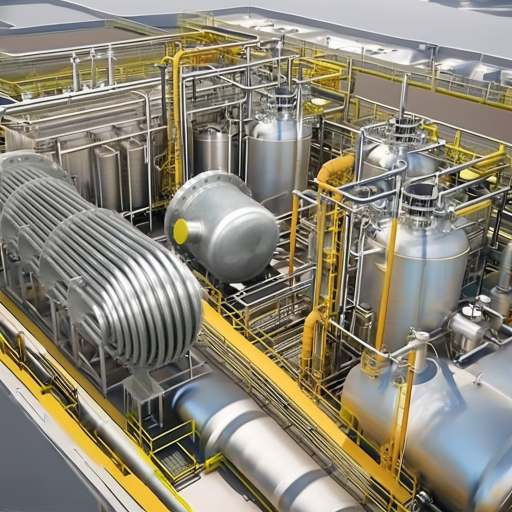
shell and tube heat exchangers will win in any application that requires High pressure, dirty fluid, or large duty. According to heat exchanger market analysis by Mordor Intelligence, shell and tube units accounted for 35.4 percent of total heat exchanger revenue in 2025 – yet remain the single largest exchanger family by sales.
| Industry | Typical service | Common TEMA type |
|---|---|---|
| Oil refining and petrochemical | Crude preheat trains, kettle reboilers, feed-effluent exchangers | AES, BEM, BKU; Class R |
| Chemical processing | Reactor cooling, distillation reboilers, condensers | AKT, BES, BEU; Class B |
| Power generation | Surface condensers, feedwater heaters, PWR steam generators | single-pass straight-tube; AEU |
| HVAC and refrigeration | Chiller evaporators and condensers | BEM, AEM; Class C |
| Food and dairy | CIP-cleanable heaters and coolers, milk pasteurization | BEM with stainless tubing; sanitary front header |
The market for exchangers, of course, is expanding. According GMI Insights shell and tube heat exchanger has the world sized at USD 6.9 billion in 2025, and is growing at a steady 8.3 percent compound annual growth rate through 2035. Hydrogen processing in decarbonization-driven retrofits – where high-temperature alloys such as Inconel and duplex stainless become the standard – are the fastest-growing submarket.
Shell and Tube vs Plate vs Double-Pipe: When to Choose Which

The three families of exchangers have some applications in common and never clash in others. Choosing well depends upon issues of pressure, fouling characteristics, dimensions, and accessibility.
| Criterion | Shell and tube | Plate and frame | Double pipe |
|---|---|---|---|
| Maximum pressure | Up to 600 bar (custom) | Around 25 bar (gasketed) | Up to 300 bar |
| Maximum temperature | 600 °C (alloy tubes) | 160 °C (gasket-limited) | 600 °C |
| Fouling tolerance | High; tubes can be brushed | Low; gaps clog readily | High; small surface, easy to clean |
| Footprint per kW | Largest of the three | Smallest; one-fifth to one-third of shell-tube | Linear; small duty only |
| Capital cost | Mid-range | Low to mid | Low for small duty; uneconomic above 100 kW |
| Maintenance access | Excellent with floating head or U-tube | Excellent — plates lift out | Limited; the inner pipe is hard to inspect |
The selection principle, therefore, is simple. Whatever the duty is, choose shell and tube in high pressure dirty, hot or large. Choose plate when contaminates tend to be clean, low pressure or when you want the smallest present for each kilowatt. Choose pipe double for small (a few kW) duty where the fluid is potentially damaging to gaskets. Typically most of a plant’s exchangers will be a mix.
Maintenance, Cleaning, and Tube Bundle Replacement
Your cleaning schedules are not driven by calendar, but by ef-ficiency curves. As one Eng-Tips contributor blunter put it on the fouling-factors thread: “Those intervals are variable depending upon what is causing the fouling. Cleaning is performance-driven, not calendar-driven.” Follow the approach temperature, shell-side pressure drop and tube-side pressure drop. When approach increases by more than about 5 C over the clean condition, or when pressure drop increases by more than 25 percent, although how long ago the last outage was, the plant needs clean now.
| Service | Indicative cleaning cadence | Typical method |
|---|---|---|
| Treated cooling water, demineralized water | 3 to 5 years tube-side; shell-side may never need it | Brush or rotary lance through tube ID |
| Cooling tower water, river water | 12 to 24 months | Mechanical brushing plus chemical descaling |
| Crude preheat, fouling hydrocarbons | 6 to 18 months | Bundle removal, hydroblast, sometimes incineration |
| Severe scaling or polymerizing process | Continuous online cleaning systems or 3-month outages | Sponge balls; chemical CIP |
Cleaning the outside diameter of a shell-side exchanger tube is a major operation – it requires bundle removal. If you expect to need to clean a tube you will need to pull the bundle to do it. A fixed tubesheet, therefore, cannot be used if you want to be able to pull the bundle later, so that the back header should be a U-tube or floating head from the outset.
Pulling a tube bundle on an exchanger that is designed to have the bundle removed is a very controlled operation – it is not a demolition job. Its tubesheet sits compressed against the shell flange; differential thermal cycling, gasket compression and in some cases scale cement, freezes it. Using a hydraulic tube bundle puller, a fixed flange, the plant tags a shell flange to a pull frame, the frame is anchored to the flange, hydraulic rams react against it and a draw bar encircles the floating tubesheet, thereby pulling the bundle along the shell axis, directly. Over that axis, without cocking it, or punching or damaging the tubesheet seal faces; the same way they learned to do it at Kjemded.
Failure modes that necessitate scheduled inspection are well characterized. A ScienceDirect survey of typical heat exchanger failures identifies fatigue, creep, corrosion, oxidation and hydrogen attack as the generic mechanism. Root causes are fouling, scaling, salt deposit, weld flaw, and operation outside of the design envelope. Flow-induced tube vibration is the designer’s mistake—the penalty is specified, not maintained for.
📐 Engineering Note
For the service routine shell-tube heat exchanger maintenance—bundle removal, tubesheet examination, tube replacement— the correct hydraulic puller amortizes itself in the first job. Have the main force calculations for the largest bundle matched out before sourcing hardware, and request a bundle puller specification quote from boshiya to determine sizing.
Industry Outlook
Three vectors are transforming shell and tube heat exchanger specification into 2026 and beyond. First, hydrogen and decarbonization processing is increasing alloy demand. Hydrogen heat exchangers alone were valued around USD 2.8 billion in 2025, will rise to roughly USD 5.9 billion by 2034 at an 8.7 percent compound annual growth rate, according to industry analyst insight. Specifiers preparing new units for hydrogen, e-fuel, or carbon-capture plants should consider Inconel 625, duplex 2205, and super duplex tubing early—carbon steel is rarely the best answer.
Second, AIassisted thermal design is becoming the standard. HTRI Xchanger Suite and Aspen EDR continue to the dominate commercial applications and specifications increasingly require suppliers’ calculations provided in their native formats. Backup hand-calculation is still anticipated for validation, but the slide-rule sizing days are over.
Third, the standards environment is changing. Currently, tema standards organization maintains the 10th edition (2019) as the most frequently cited hard-copy standard, with the 11th edition available as an online subscription through tema Support. ASME BPVC 2025 is the latest pressure vessel standard edition. When preparing specifications for 2026 projects, specify year-stamped editions and check with suppliers on the traceability of materials certificates to the same editions.
Frequently Asked Questions
Q: What is a shell and tube heat exchanger used for?
View Answer
shell and tube heat exchangers transfer heat from one fluid to the another in oil refineries, chemical plants, electric power stations, HVAC chillers, ships’ engines, and food manufacturing facilities. They operate at higher pressures (to 600 bar) and more contaminated fluids than plate exchangers, and that is why they remain the most-installed heat exchanger type across high-capital-weight heavy industry.
Q: Why is a shell and tube heat exchanger better than a double-pipe heat exchanger?
View Answer
A shell and tube design allows dozens of each parallel tube into a single shell, providing order of magnitude more Pipimis H-Kiver area per square meter of plot area than a double-pipe exchanger. Double-pipe units are cost-effective only for small duties (less than about 100 kW). For anything larger, shell and tube wins on both capital and maintenance cost.
Q: Which side should the hot fluid be on, shell or tube?
View Answer
Hot side does not dominate allocation; the more contaminated, more corrosive, and higher pressure process fluid must go on the tube side. The tubes are more accessible for cleaning, inspection, and replacement than the shell. The Noyis Mekodes will go on the cleaner low-pressure process. The direction of heat flow will follow whichever option the safety and maintenance considerations privilege.
Q: How often should I clean a shell and tube heat exchanger?
View Answer
Based on performance not calendar guidelines, Run clean based on approach temperature. Enter a clean when approach temperature exceeds about 5 o C of the cleaned baseline, or when pressure drop exceeds 25 percent. Service for treated water may be three to five years between cleanings. Crude preheat or scaling cooling water may require outage on every 6 to 18 months.
Q: What is a 1-2 shell and tube heat exchanger?
View Answer
This uses a 1-2 exchanger with 1 shell pass and 2 tube passes. The fluid on the shell side passes once, while the tube side fluid runs from the front header to the rear header, then back through the remaining path, and leaves the front. This is a common layout because inlet and outlet tube nozzles are on the same end, leaving an easy piping run. The drawback is that the flow is not true countercurrent, so the average U will need correction with an F-factor.
Q: What is a shell and tube heat exchanger in HVAC?
View Answer
In HVAC plant rooms, shell and tube heat exchangers as Evaporators in chillers and condensers are used, where refrigerant boils or condenses on one side, while water flows on the other. They are also used as plate-and-frame replacements for high pressure or fouling resistance in the chilled water loop. tema Class C designations are typical for HVAC applications.
About This Guide
This shell and tube heat exchanger guide brings together design data and best operational practices from tema 10 th Edition, ASME BPVC Section VIII, as well as peer-reviewed sources, Thermopedia and ScienceDirect. Recommendations for life walking and fluid distribution are based on those found in published Eng-Tips engineer threads. Verified by the boshiya engineering team for shell and tube heat exchanger service and maintenance.
References & Sources
- tema standards (10 th Ed., 2019; 11 th Ed., online) – Tubular Exchanger Manufacturers Association
- Shell-and-tube heat exchanger – Wikipedia (citation both from tema, ASME BPVC, and the Energy Institue)
- shell and tube heat exchangers – Brogan, R.J., Thermopedia (HTFS Harwell Laboratory; DOI 10.1615/AtoZ.s.shell_and_tube_heat_exchangers)
- ASME Boilers and Pressure Vessels Code, Section VIII, Division 1, Part UHX – American Society of Mechanical Engineers
- Static Equipment: Understanding heat exchangers – Society of Petroleum Engineers, Journal of Petroleum Technology
- Failure modes in various heat exchangers – ScienceDirect, Engineering Failure Analysis
- Generic Overall heat transfer Coefficients (U-values) – Engineering Page
- Market report for Shell & Tube heat exchanger 2026-2035 – GMI Insights
- heat exchanger Market Report (Size, Share & Forecasts) 2031 – Mordor Intelligence
![ASME Pressure Vessel Fabrication Guide: Section VIII Requirements [2025]](https://boshiya.com/wp-content/uploads/2026/05/2-46-150x150.webp)