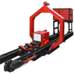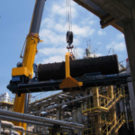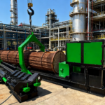
Get in Touch with BOSHIYA


Bundle Puller: The Field Engineer’s Guide to Types, Procedure, and Equipment Selection
Quick Specs
| Pull Capacity Range | 5–150 tons |
| Max Bundle Length | 5,000–15,000 mm |
| Frame Diameter Range | 500–3,200 mm |
| Power Options | Diesel / Electric / Hydraulic |
| Control | Remote wireless operation |
| Standards | API 660, ASME Sec VIII, TEMA |
A bundle puller is hands-down the single most valuable machine during a heat exchanger turnaround — and for whatever reason, one of the least appreciated. Part of a complete upgrade to a heat exchangers’ reliability, this article will show you how they operate, what style is best for your specific conditions, and the precise processes that have kept most unique ex-changer extractions on schedule and under budget. If your refinery or petrochemical plant relies on shell-and-tube exchangers, it pays to sharpen your critical equipment knowledge base.
What Is a Bundle Puller?
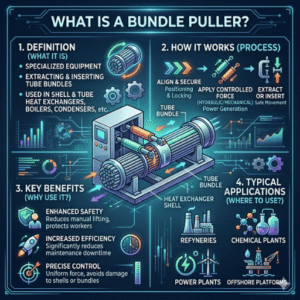
A tube bundle puller is a hydraulically-driven piece of machinery used to remove tube bundles from shell-and-tube exchangers either as part of maintenance or inspection, or when replacing a heat exchanger. It clamps onto the tube sheet or a dedicated pulling ring, and applies carefully metered horizontal force in order to slide the bundle out of the shell at speeds typically somewhere between 0.3 meters/minute (slow pull) and 1.5 meters/minute (fast pull).
Important to understand is that this is completely different equipment to cable or wire bundle pulling equipment often employed in wiring installations. This is heavy industrial maintenance equipment designed specifically for this task. Refineries, petrochemical complexes, power generators and LNG (liquefied natural gas) terminals all depend on them during almost every turnaround cycle. Each product in the bundle puller range serves a specific heat exchanger maintenance application, from small tube bundles under 5 tons to large industrial units exceeding 100 tons.
Why not simply use a crane? Three reasons. One, many shell-and-tube heat exchangers are housed inside pipe-racks or other isolated structures that mount cranes too far away for load accuracy. Two, a crane will force vertical application of the horizontal load to the bundle – risk destroying the shell bore or baffle support tabs. Three, turnaround speed. Cranes do not speed-load as quickly or easily as dedicated squeeze-lift systems. Such hardware performs about twice as many efficient tube bundle extractions per shift.
💡 Key Numbers
Vertical lifting capacity of bundle-pulling machines varies from 5 tons for small process fixed-exit Ex-changers, up to 150 tons for large BTX (benzene-toluene-xylene) applications. Common industries deploying them include oil refining, petro-chemicals, power generation, LNG/Gas processing, pulp and paper, marine-vessels. Large refineries (more than 200 process heat exchangers) can expect to schedule 40-60 bundle extractions per turnaround.
BOSHIYA supplies a complete line of bundle puller solutions capable of applying loads from 25–150 tons, covering the full spectrum of shell-and-tube heat exchanger markets operating in the downstream and midstream sectors.
How Tube Bundle Extraction Works — Mechanics and Force Calculation
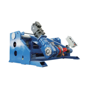
The function is simple hydraulics. A diesel drive or 220V electric motor drives a hydraulic pump which pressurizes a quantity of oil and feeds it to one (or several) hydraulic cylinders. A hydraulic cylinder applies linear force to a component. The component may be any type of barreled plunger, reciprocating ram or other actuator design. The cylinder applies this force to whatever one end is mechanically fixed – in this case a ring that surrounds a heater bundle (or the faces of the tube sheet for a fixed-End Exchanger).
Activation of the setup results in the hydraulic cylinder either extending or retracting, depending on which mode is selected, in order to pull the bundle out of the shell along its longitudinal axis. Most newer package systems employ a dead-straight guide rail to keep the tube bundle perfectly aligned during extraction. The tube bundle glides on rails or rollers kept along the path in order to reduce drag.
Force Requirements
According to ScienceDirect’s engineering references, a device supporting horizontal bundle pull loads must be able to exert a pulling force of 1.0 x the weight of the removable tube bundle, minimum 2,000 lb (9.0 k N). This the bare minimum. The actual pull force required is nearly always far greater; due to friction.
There are three friction factors that result in the true pull force on site being well above the theoretical minimum. Corrosion film build-up between the bundle outer tube surfaces and the shell bore can raise friction coefficients from 0.15 (clean carbon steel against a clean carbon steel surface) to 0.4+, as fouling deposits such as scale, coke, biofilms act as an adherent in a long run time (4+ years). Gasket compression between the tube sheet and shell flange can also cause bundle binding, especially if the retainer bolts were initially over tightened during assembly and have not loosened over time.
📐 Engineering Note
Pull Force Estimate: Fpull = Wbundle × (1 + μfriction), where μ ranges from 0.15 (clean recently serviced) to 0.5+ (heavily fouled, 6+years run time). For a 30-ton bundle with moderate fouling (μ = 0.3), the required pull force is roughly 39 tons. Always build in a safety factor of 20% over the theoretical value for safe equipment sizing. A pre-pull inspection via borescope of shell bore conditions and fouling history can prevent under-sizing your puller on site.
Work pressure for the hydraulic systems is normally between 200 bar and 350 bar. Cylinder sizes are from 150 mm bore on light duty units to 300+ mm bore for heavy duty models. Stroke travel per cycle can be from 300 mm up to 1500 mm allowing the puller to reach across large equipment and getting several pulls from the rail system assuming the rack and pinion will go further than 1 stroke each cycle.
Types of Bundle Pullers: Diesel vs Electric vs Aerial
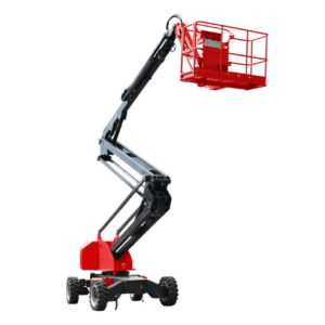
Bundle pullers can be divided into 4 groups, based on the type of environment they are designed for. Selecting the incorrect type results in different delays, safety hazards and congestion on your turn around schedule.
Diesel Bundle Pullers
Diesel driven units form the core of the outdoor turnaround. As they generate their own source of power, usually a 53 k W diesel engine, they are fully independent of any electrical power sources, perfect for remote locations, offshore platforms or green field developments until a switchboard is installed for operational use. They will generate off site emissions which makes their operation unsuitable for process areas enclosed spaces.
Electric Bundle Pullers
Electric units operate on 3 phase electrical power, commonly 380-480V. They generate no off site emissions and are required by majority of LNG facilities, hazardous process areas and emission abatement centers. They require between 37-75 kW depending on their size of capacity. They are significantly quieter than diesel, 72-78 d B at 1 meter rather than 85-95 d B at 1 meter.
Aerial / Crane-Mounted Bundle Extractors
Hot, heat exchanger arrays are frequently located 10 – 20 meters above grade and require a crane boom or dedicated mast with an aerial bundle extractor mounted. They sacrifice some free pulling capacity, typically max 100 tons to allow for elevation changes. The actual bundle pulling still occurs horizontally, effectively the bay must be able to move the crane to place the boom at the correct elevation, then allow hydraulic cylinders to do the pulling.
Self-Propelled Units
Self-propelled bundle pullers pair a mobile chassis with the hydraulic bundle extraction system. These units travel under their own power between exchangers rather than rely upon the deployment of a dedicated transport vehicle. Self-propelled bundle pullers tend to be prevalent within extensive refinery complexes with 20+ exchangers scheduling service within a particular turnaround window.
Comparison Table
| Feature | Diesel | Electric | Aerial |
|---|---|---|---|
| Capacity Range | 25–150 tons | 30–150 tons | 5–100 tons |
| Typical Power | 53 kW | 37–75 kW | 30–55 kW |
| Max Bundle Length | 15,000 mm | 15,000 mm | 12,000 mm |
| Emissions | Yes (exhaust) | Zero | Zero |
| Best For | Outdoor / remote sites | Indoor / emission zones | Elevated pipe racks |
| External Power | Not required | Required (3-phase) | Not required |
Diesel Bundle Puller — Advantages and Limitations
✔ Advantages
- Self-contained power — no site electrical hookup needed
- Operates in remote locations, offshore platforms, and greenfield sites
- Reliable performance within the extreme range of –20 °C to +50 °C
- Faster mobilization — drive-up deployment in under 30 minutes
⚠️ Limitations
- Exhaust emissions — prohibited in enclosed or emission-controlled areas
- Noise level production: 85-95 dB at 1 meter (hearing protection necessary)
- Fuel handling issues – availability of on-site diesel fuel supply as well as spill containment infrastructure
- Higher ongoing fuel cost vs electric operating cost
Electric Bundle Puller — Advantages and Limitations
✔ Advantages
- Reduced localized on-site emissions – certified for LNG, indoor and emissions restricted areas
- Reduced noise levels: 72-78 dB at 1 meter (able to converse at 3 meters)
- Reduced operating expenses – comparably equipped electric units can realize 30-45% savings when compared with upon-site diesel fuel costs
- Reduced vibration levels – advantageous in reducing operator fatigue in long, labor-intensive workdays
⚠️ Limitations
- Requires 3-phase power supply (380–480V) on site
- Power cable management adds setup complexity
- Not suitable for remote/offshore locations without on-site grid power.
- Voltage compatibility must be verified for existing site infrastructure (50 Hz vs 60 Hz)
Since BOSHIYA manufacturers matching capacity class electric and diesel driven bundle pullers, it is unnecessary to reconfigure tooling or mountings with switching between power types. The hydraulic drive system on both diesel and electric models delivers efficient bundle extraction with remote operation capability, making them standard refinery maintenance equipment.
Bundle Pulling Procedure: Step by Step
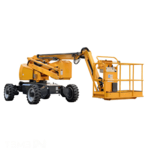
A safe, systematic bundle pull involves the repetition of a carefully determined order of operations. Tooling, step progression, and a strict adherence to the following 7-step procedure will keep both harm and schedule delays to a minimum when removing shell-and-tube heat exchanger bundles in horizontal orientation. (The procedure focuses upon common refinery and petrochemical applications comprised primarily of shell-and-tube heat exchangers and thus does not account for heavy superfouled units and other speciality circumstances.)
- Isolate and lock out all energy sources. Follow OSHA 29 CFR 1910.147 Lockout/Tagout (LOTO) requirements. This covers process fluids, electrical power to pumps, steam supply, and instrument air. Each worker in the extraction zone must apply their own lock. Verify zero-energy state with pressure gauges and voltage testers before proceeding.
- Drain and depressurize the heat exchanger. Open low-point drains on both shell and tube sides. Confirm zero pressure on both sides using calibrated gauges — do not rely on control room readings alone. For exchangers handling hydrocarbons, test for residual vapor with a combustible gas detector. Water-flush if the process fluid leaves hazardous residue.
- Unbolt the channel cover and expose the tube sheet. Remove bolts in a star pattern to release flange stress evenly. On large exchangers (shell diameter >1,200 mm), use hydraulic bolt tensioners rather than impact wrenches to prevent flange face damage. Set bolts aside in labeled containers for reassembly.
- Inspect the tube sheet face. Check for corrosion pitting, gasket groove damage, tube-to-tubesheet joint leaks, and erosion patterns. Document findings with photographs. This inspection takes 15–30 minutes and frequently reveals conditions that affect reassembly — skipping it leads to repeat leaks after the turnaround.
- Attach the bundle puller and align with the shell centerline. Position the puller frame so the pulling axis is within ±3 mm of the shell bore centerline. Secure the pulling head to the tube sheet pulling ring or directly to the tube sheet face using the appropriate adapter.
⚠️ Warning: Misalignment during extraction is the single most common cause of shell bore scoring and baffle damage. A 5 mm offset at the tube sheet can translate to 15+ mm of lateral deviation over a 10-meter bundle length. Always verify alignment with a laser pointer or string line before applying any hydraulic force.
- Apply controlled hydraulic force to extract the bundle. Begin with a low-pressure test pull (10–15% of rated force) to break initial static friction. Monitor pull force on the hydraulic gauge — a sudden spike indicates an obstruction. Extraction speed should not exceed 1.5 m/min. Support the bundle on rollers as it exits the shell to prevent sagging and tube damage.
- Transport the bundle to the cleaning or inspection area. Use the puller’s integrated rail system or a bundle transporter to move the extracted bundle. Never drag a bundle across bare ground — this bends tubes and damages baffles. A typical turnaround crew completes 5–6 bundle pulls per 10-hour shift using this procedure.
Pre-Pull Inspection Checklist
- All lockouts verified: indicator lights active, locks secured, switches disconnected, zero energy presence confirmed.
- ✔ Both shell and tube sides drained and depressurized
- ✔ Atmospheric testing complete (LEL, O₂, H₂S if applicable)
- ✔ Channel cover and bonnet removed, tube sheet exposed
- ✔ Tube sheet face inspected and documented
- Self-propelled bundle puller within 3 mm of true shell centerline.
- Hydraulic hoses inspected for damage and tripping hazards: no bulges, cuts or leaks.
- ✔ Support rollers positioned along extraction path
- ✔ Wireless remote control tested and functional
- Pre-established exclusion zone: no personnel within definitive bundle removal path.
How to Select the Right Bundle Puller Equipment
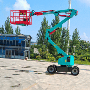
Purchasing the appropriate bundle puller ultimately boils down to a balancing of four distinct measures: capacity, bundle length, power source and accessibility. Improper selection will result in either a machine incapable of doing the required work or a missized model whereby the available space around the exchanger presents the home for an oversized equipment solution.
1. Capacity
Begin with the heaviest tube bundle on the worksheet. Add the weight of any attached floating head or backing ring. Adjust for friction: multiply by 1.3 for newly serviced exchangers, as much as 1.5 for hundreds of thousands of running hours with known accumulation. That figure indicates the minimum pull force needed.
💡 Sizing Tip
Always opt for a bundle puller capacity rating in excess of 20% of the heaviest anticipated bundle pull force. This will provide margin of safety in accommodating real-world fouling levels and corrosion growth seen during service, as well as one of the fundamental hydraulic expert testimonials – use equipment at 20% capacity with an expectation of 80% maximum to rise to 120% cylinder seal life of running time relative to maximum.
2. Bundle Length
Determine the dimensions of the longest tube package in the rental or service scope. Ensuring a purchased units’ base rail system will support its installation along the full length of the tube bundle’s path is critical: long — left to right.
3. Power Source
If you’re working outdoors and there are no restrictions on emissions, the diesel gives you the most options. Working indoors, LNG plants, or in any facility with emissions monitoring means electric. Some sites require both – electric for the process building units, diesel for the tank farm exchangers. Dual-power machines exist but are more costly and complicated to operate.
4. Site Access
Now determine access to each of the exchangers within your scope. One point for each direction, check road width, overhead clearance, floor loading strength and turning radius at angles. Take a 150 ton puller with a full rail system. The diesel weighs 15-20 tons and measures 12+ meters in transport configuration. If your exchangers are elevated on pipe racks, an aerial bundle extractor may be your only choice.
Rent vs Buy Analysis
For fleet buys with multiple turnaround cross-sites, the buy-vs-rent break-even point traditionally is about 14 months of aggregate rental costs, after which ownership makes more financial sense. Allow 10-15% of purchase price annually for maintenance if purchasing. Single-site operators with a turnaround at 3-5 year intervals probably will find renting the best approach.
Rent is classified by capacity class, region, and other variables. Electric units in the 60-ton range being rented in North America at a cost of about $8,000-$15,000 per month. Diesel units of 150-ton capacity go for around $18,000-$30,000 per month. While including basic operator instruction, these costs generally do not factor in mobilization/demobilization transportation costs.
Check out our full bundle puller range in all capacity classes from 25T to 150T to determine the best match for your scope and access. Specifications include dimensional drawings.
Safety Standards and Inspection Protocols
As a point where heavy lifting intersects with pressure vessel construction and possibly hazardous atmospheres, bundle pulling is regulated by many standards. Part of the refinery maintenance professional’s role is to distinguish which standard applies to which aspect of a particular job.
Applicable Standards
Shell-and tube type heat exchangers are designed and fabricated to API Standard 660. Included in its stipulations are the requirements that roll edges (rails supporting the bundle inside the shell) have be rounded or beveled to prevent damage to the tubes while pulling. A specification for a multiple piece pulling attachment (pulling lug) is also documented therein.
Before any bundle is pulled, adherence to the Lockout and Tagout standard (OSHA 29 CFR 1910.147) is mandatory. All energy sources (thermal, process fluid, electrical, pneumatic) must be isolated and secured prior to the removal of the bundle. Lotoc procedure reviews are conducted annually.
OSHA 29 CFR 1910.146 pertains to permit-required confined spaces. If an exchanger shell (after bundle removal) must be entered by personnel, a confined space permit, administrative authorizations, atmospheric monitoring, and rescue provisions are mandated.
ASME Section VIII Division 1 covers the design specifications of the pressure vessel. The bundle puller must not impose forces greater than the shell’s design load limits, especially at nozzle connections and saddle supports.
TEMA Standards organize exchangers by type (refinery, chemical, general) and list general mechanical design parameters such as tube sheet thickness, baffle spacing, and support plate dimensions which define extraction clearances as well.
Pre-Operation Safety Checklist
- LOTO used and checked individually by each crew member
- Atmospheric test complete – LEL <10%, O₂ 19.5–23.5%, no toxic gases above PEL
- Confined space permit issued (if shell entry required after extraction)
- Hydraulic system checked for leaks, hoses within service life
- Puller frame and rail system checked for structural integrity, bolts torqued
- ✔ Wireless remote control range-tested from planned operator position
- Barricaded exclusion zone – no closer than 3 meters to pull path
- ✔ Emergency stop tested and functional
⚠️ Hazard Alert: Stored Energy
Although drained and depressurized, heat exchangers can contain stored thermal energy and trapped pockets of pressure. For example, a shell which ran at 300 °C may still have surface temperatures above 60 °C several hours after shutdown. Residual pressure can be trapped behind closed valves, blocked drain lines, or debris which forms an effective temporary seal. Always check to ensure zero pressure and safe temperature (<50 °C surface) before having personnel near the tube sheet face.
Maintenance, Troubleshooting, and Lifecycle Cost
the bundle puller is a hydraulic press operating in the hostile environment of the power plant. When the maintenance team are not running a disciplined program, even the most durable hydraulic presses suffer from performance loss. Data from Valmet’s hydraulic maintenance research shows that reactive maintenance, repairing the burst after initial occurrence, costs three to five times more than preventive maintenance during the equipment’s lifecycle.
Maintenance Schedule
| Interval | Tasks |
|---|---|
| Daily | Hydraulic fluid level check, visual leak inspection of all hose connections and cylinder seals, wireless remote battery check |
| Weekly | Hose and seal condition check (look for abrasion, cracking, bulging), rail alignment verification, grease all moving joints |
| Monthly | Full component audit, hydraulic filter replacement, oil sample analysis for contamination, cylinder rod inspection for scoring |
| Annually | Complete system overhaul, cylinder rebuild (seal kits + rod inspection), all hose replacements if >5 years old, structural weld inspection |
Lifecycle Cost Data
there is an enormous difference between planned and reactive maintenance. For example, a planned hydraulic pump reconditioning will cost $3,000-$8,000 in parts and labor and can be scheduled during a planned outage, with no downtime. Whereas, an unplanned, mid-turnaround pump failure will set $15,000-$40,000 or more in parts, plus heavy labor hours and knock-on effects on the timing of the turnaround for each day the tube bundle remains inoperable in $50,000-$200,000.
Allow 10-15% of the bundle puller purchase price per year for maintenance. On a $250,000 machine that equates to $25,000-$37,500 per annum. Hydraulic hoses should be changed on a routine basis every 5-7 years, regardless of appearance, as the internal rubber ages prematurely. Proper removal and replacement of worn components keeps the extraction system reliable across its full service life.
💡 Troubleshooting Pro Tip
Look for the following early warning signs, rather than expensive breakdowns:
- slow pull speed when operating at the maximum system pressure – is an early warning sign of internal cylinder bypass (worn seals) or pump cavitation. Check the oil level and condition of the seal and packings.
- sudden ups and downs in pressure whilst pulling the bundle – reveals that the bundle is snagging on a deflector or the bored out section of the shell. Stop and reposition.
- hydraulic oil temperature in excess of 80 °C – indicates an undersized, blocked or over capacity oil cooler. Running at a temperature too high to was seal prematurely with a 50% faster degradation rate for every 10 °C increase.
- wireless remote responds inconsistently – change the batteries first. If the fault remains, there is RF interference, potentially from welding or radio transmitter equipment. Always carry a wired backup pendant.
Frequently Asked Questions
Q: What is bundle pull load and how is it calculated?
View Answer
The bundle pull load is the combined force required to pull a tube bundle out of the heat exchanger shell. This force is equal to the weight of the bundle times a friction factor that is affected by corrosion, fouling and the interference fit of the heat exchanger tube sheet. ASME and other industry standards specify that the structure supporting the heat exchanger be able to support at least 1.0 times the weight of the bundle (equivalent to 2,000-lb absolute floor support regardless of the actual load) and ideally support at least 2.0 times the weight of the bundle. In practice, the net pull force after mechanical interference and fouling correction is on the order of 1.3-1.5 times the true heat exchanger bundle weight. Always allow a 20% overhead above the calculated working force when selecting equipment.
Q: How do you remove a tube bundle from a heat exchanger?
View Answer
Removing a tubular bundle. Requires a 7 step process: power off and lock out, gravity drain and mechanical depressurization of the heat exchanger, unbolt and remove the channel cover, examine the tube sheet, align and attach the bundle puller and make it level with the centerline of the heat exchanger shell, machine the hydraulic force to slowly pull the bundle out of the shell, and pick up or reposition the tube bundle. Takes 2-4 hours per heat exchanger depending upon size and fouling condition.
Q: What is the difference between a bundle puller and a bundle extractor?
View Answer
In the majority of industrial settings “bundle puller” and “bundle extractor” are used synonymously to refer to a hydraulic device that pulls tube bundles out of a heat exchanger shell. “Bundle extractor” is more the term seen in professional engineering specs and catalog literature, where “bundle puller” tends to be used on site in the field. One distinction is that “aerial bundle extractor” refers to a crane-mounted bundle pulling vehicle that accesses pipe racks from above, and is not converted or calling itself an “aerial bundle puller”.
Q: Can a bundle puller handle small tube bundles under 5 tons?
View Answer
YES. Although the majority of industrial bundle extractors are rated 25T and above, smaller hydraulic extraction devices rated at 5-15T capacity are used in pharmaceutical, HVAC, and food processing plants on compact heat exchangers. For bundles that don’t exceed 5T, some companies use a combination of small hydraulic jacks and manual chain-sets, although the safety margins and alignment accuracy are far superior with a purpose-built machine.
Q: How often should a bundle puller be inspected?
View Answer
An automated schedule of inspections which begins with routine daily fluid and remote control health checks and weekly hose and seals checks, progresses through monthly component audits with filter change and oil sample, and culminates in annual refresh of all component parts and structural elements including cylinder rebuilds and weld inspections. Hose changes every 5-7 years regardless of appearance. Exterior mechanical and electrical equipment should be fully inspected immediately prior to use in each turnaround even if machine is stored all others months of the year.
Q: Is it more cost-effective to buy or rent a bundle puller?
View Answer
It depends how many heat exchangers you plans to provide siting engineers with a unit in the future. For example, in North America it takes about 14 months of rental costs (accumulated across several sites) for a fleet operator to reach a net cash positive any event purchase; after 14 months of rental a purchased machine is the lowest cost option. Allow for 10-15% of the purchase price in yearly maintenance costs. For single-site operators with heat exchangers on 3-5 year turnaround cycles rental will almost always be financially superior. Rental prices for a 60T electric powered unit are about $8,000–$15,000 each month while a 150T diesel powered unit rents for $18,000–$30,000 each month. Add on mobilization, special training, etc.
Need a Bundle Puller for Your Next Turnaround?
BOSHIYA Group manufactures diesel and electric bundle pullers from 25T to 150T capacity with complete customization available.
About This Guide
Since 1895, BOSHIYA has been producing heavyduty industrial equipment such as thehydraulic bundle puller systemsandheat exchanger maintenance systemsfor use in refineries, petrochemical plants and LNG terminals globally. This document is synthesized from field engineer information gathered during refinery turnaround operations and industrial published standards. Equipment specification referenced pertains to BOSHIYA current deliverybundle pullerends rated at 25-150ton.
Related Articles
References & Sources
- ScienceDirect — Bundle Pull Overview (sciencedirect.com)
- API Standard 660: Shell-and-Tube Heat Exchangers — American Petroleum Institute (api.org)
- OSHA 29 CFR 1910.147: Control of Hazardous Energy (Lockout/Tagout) — U.S. Department of Labor (osha.gov)
- OSHA 29 CFR 1910.146: Permit-Required Confined Spaces — U.S. Department of Labor (osha.gov)
- ASME Boiler and Pressure Vessel Code, Section VIII Division 1 — American Society of Mechanical Engineers (asme.org)
- TEMA Standards — Tubular Exchanger Manufacturers Association (tema.org)
- Valmet — Hydraulic Maintenance Schedule Best Practices (valmet.com)
![Polypropylene Resin: Grades, Types & Selection Guide [2026]](https://boshiya.com/wp-content/uploads/2026/05/0-150x150.webp)