Get in Touch with BOSHIYA

How to Clean Shell Side and Tube Side of Heat Exchangers: A Maintenance Field Guide
Contents
show
A shell and tube heat exchanger that operated at maximum heat transfer efficiency six months ago could now be costing your facility thousands of dollars in excess energy expenses—and the cause is fouling™ more than 99% of the time. Deposits build up on both the tube side and the shell side, but each build-up zone has a different cleaning challenge. This article separates proven cleaning procedures for both sides, evaluates how they differ, and illustrates the trade-offs and selection criteria that maintenance operators at refineries, chemical plants, and powerhouses apply in the field.
Whether you’re cleaning calcium carbonate deposits inside the tubes or hydrocarbon build-up around the shell side baffle plates, the type of cleaning you use impacts how much heat transfer you recover—and how fast your heat exchanger returns to operating condition.
Why Shell Side and Tube Side Fouling Is a Billion-Dollar Problem
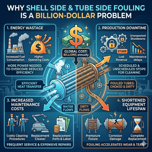
Cleaning of shell and tube heat exchanger is not an afterthought—a part of the ownership costs of a plant. When deposits accumulate on heat exchanger tubes or on the shell side baffles, heat transfer resistance rises, pressure drop increases, and the unit degrades toward derating mode.
0.25%
of GDP lost to fouling in industrialized nations
$4.4B+
estimated annual fouling cost across major industrial nations
35.4%
market share held by shell-and-tube designs in 2025
U.S. Department of Energy data compiled at Oak Ridge National Laboratory estimates fouling incurred by American industry alone at hundreds of dollars annually in consume fuels, unseated maintenance events, lost throughput, and reduced output. Muller-Steinhagen estimates the impact at roughly 0.25% of GDPs in developed economies, or over $4.4 billion in the collective United States, United Kingdom, Germany, and Japan markets.
Cost of damage divides into two categories. Mineral scaling, biological growth, and entrained deposit in the tubes—tube side fouling—limited throughput and insulates the heat transfer surfaces. Hydrocarbon coking, corrosion deposits, or entrained sediments between baffle plates—shell side fouling—is less obvious, and tends to cause more damage because the shell side is a more difficult piece of equipment to open.
⚠️ Common Misconception
Many operators assume the shell side isn’t foulping as much because it’s cooled with water. In fact, process circulating fluids in the shell side generally contain higher concentrations of heavy hydrocarbons, wax, or polymeric deposits that adhere tightly to the tubes exterior walls and baffle edges—and pull off less easily with standard cleaning techniques.
Shell Side vs Tube Side — What Makes Each Cleaning Challenge Different

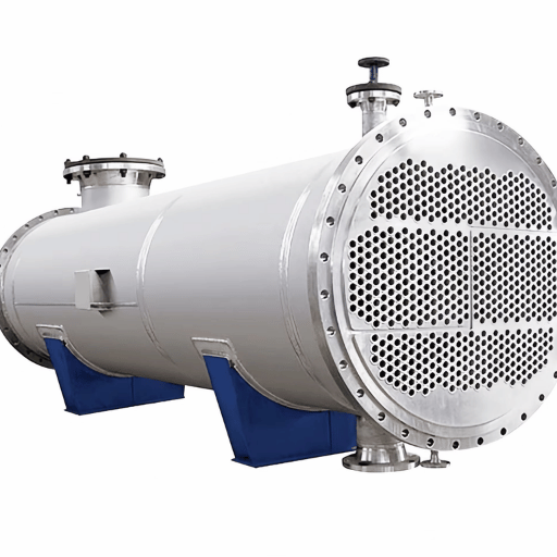
Before choosing a cleaning technique, operators must recognize how the shell side and the tube side of a shell and tube heat exchanger differ fundamentally. Heating and cooling channels in the tube side are well separated by the tube structure, avoiding build-up of intervening deposits when properly cleaned. By contrast, a shell side rounds the outside of the tubes, flow-accelerating curvatures and baffle gaps, coiled into a serpentine path that hampers access and limits cleaning intensity.
| Factor | Tube Side | Shell Side |
|---|---|---|
| Physical access | Direct — remove bonnet, insert lance or brush inside of the tubes | Restricted — baffles, tie rods, and tube bundle geometry block straight-line entry |
| Common fouling types | Mineral scaling, water scale, biological growth, particulate deposit | Hydrocarbon coking, polymer residue, corrosion products, sludge accumulation |
| Bundle configuration impact | Minimal — all tube configurations allow tube side access | Major — fixed tubesheet designs make shell side access nearly impossible without chemical circulation |
| Removable bundle option | Not required for tube side cleaning | Floating head or U-tube designs allow bundle extraction for external shell side cleaning |
| Detection difficulty | Moderate — pressure drop across tube side is a reliable indicator | High — shell side fouling often undetected until thermal performance drops noticeably |
| Typical cleaning time | Hours (mechanical) to 1–2 days (chemical) | 1–5 days depending on access and fouling severity |
Your choice of configuration – fixed tubesheet, floating head, or U-tube – will influence the available cleaning methods. A stripped-down bundle design allows operators to remove the tube bundle and clean both sides externally. Fixed tubes keep the shell side internals – teams can only rely on chemical circulation or specialized robotic kit to fouling without dismantling.
💡 Pro Tip
When selecting a new heat exchanger, think about future maintenance access. According to the experience of both chemical and petrochemical refineries, floating head units are 15-20% more expensive initially but deliver much lower life-of-shell side cleaning costs thanks to the bundle being accessible for external washing.
Tube Side Cleaning Methods — Chemical, Mechanical, and Automated
heat exchanger tube cleaning generally falls into one of three categories, each suitable for different deposit types, tube materials, and turnaround schedules. To make the right choice, comprehend what is fouling the inside of your tubes, how tenacious the deposit is, and how fasty you need your unit back in service.
Chemical Cleaning
chemical cleaning circulate is pumping an acid solution, alkaline solution, or solvent through the tube side to remove deposits without physical contact. Well-known chemicals include hydrochloric acid (HCl) for mineral scaling, sodium hydroxide (NaOH) for organic fouling, and citric acid for light water scale on stainless steel heat exchanger tubes. Cleaning takes from 4 to 24 hours depending on the deposit action required and the volume of chemical used.
The process of acid cleaning even during corrosion control studies (ScienceDirect) makes it critical to keep inhibitors flowing so the acid doesn’t foul the tube material. Particularly in the case of exchanger tubes stainless steels, the presence of chlorides in chemical can trigger stress corrosion cracking – an eventual failure that can’t be seen until your tube explodes.
Mechanical Cleaning
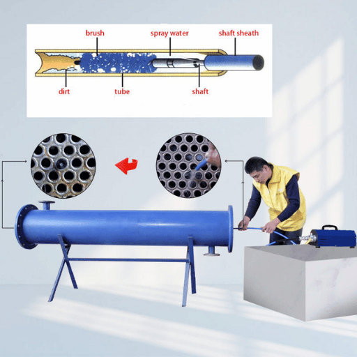
Mechanical heat exchanger tubes cleanings entail physically dislodging fouling using wire brushes, scrapers, or drill-type cleaners inserted through each tube bore. An operator pushes the tool through each tube individually, giving impressive results on hardite fouling and calcium or biological fouling that won’t succumb to chemical.
When batch cleaning fouling, a technique called hydroblasting also called hydro blasting is used to propel water at high pressure up to 40,000 PSI through a lance and nozzle. The jets remove fouling from the tube internals without the chemical usage required with acid-washing. Semi-automated multi-lance units will clean three-to-one faster than manual lancing with single-lance units based on equipment specifications from cleaning manufacturers.
Automated Tube Cleaning Systems
Automated heat exchanger tube cleaning systems use multiple units of multiple lance – one, two, three, and five at once – operated remotely or from a manned console. A tube side bundle cleaner protects operators from high-pressure water exposure and increases cleaning speed by anywhere from 50-75% over manual single-lance systems.
| Method | Best For | Pressure Range | Turnaround Time | Waste Handling |
|---|---|---|---|---|
| Chemical cleaning | Scaling, organic films, fixed tubesheet units | N/A (circulation) | 4–24 hours | Hazardous chemical disposal required |
| Manual lance / brush | Light to moderate fouling, small bundles | 10,000–25,000 PSI | 1–3 days | Water only (minimal waste) |
| Automated multi-lance | Large bundles, heavy fouling, tight turnarounds | 10,000–40,000 PSI | Hours to 1 day | Water only |
- ✔
Ensure tube material (sanity check the specifications table for carbon steel, stainless steel, and alloy steel grades) - ✔
Check tube wall thickness (UT gauging) before hydroblasting above 20,000 PSI. - ✔
Always block and bleed the process during channel head access. - ✔
Use the correct equipment rated for the operating pressure – never exceed nozzle PSI rating
Shell Side Cleaning Methods — From CIP to Robotic Jetting

shell side is the more challenging half of any heat exchanger cleaning job. shell side geometry – tubes packed in rows with baffle plates every 6 to 24 inches – creates dead zones where fouling collects and conventional cleaning devices cannot reach. Three key approaches address this challenge, each with varying access requirement and fouling removal efficiency.
Chemical Circulation (CIP)
Clean-in-place (CIP) cleaning circulates chemical solutions up to the shell side without removing the tube bundle. A pump drives the cleaning chemical – often a caustic or acid solution – through the shell inlet, around the baffles, and out the discharge line. This approach is best used on soluble deposits such as light scaling or biological fouling. For fixed tubesheet exchangers in which the bundle cannot be extracted, CIP may be the only practical option for shell side cleaning.
Reach is where CIP fails. Chemical solutions follow the path of least resistance, which means thickly fouled zones between tightly spaced baffles tend to receive poor circulation. operators must carefully calibrate flow rate, temp and soak time to ensure the chemical contacts all fouled surfaces. dispose of used chemicals according to local environmental regulations – though most acid and caustic solutions require neutralization before discharge.
High-Pressure Water Blasting
When the tube bundle is removable, high-pressure water blast cleaning targets the shell side from the outside. An operator directs water jets between tube rows by way of a handheld lance or a stationary nozzle carriage. Operating pressures typically range from 10,000 to 25,000 PSI with flowing water volumes of 10-100 gallons per minute.
Traditional shell side water blasting has a serious drawback: the baffle plates and tightly packed tube-to-tube gaps limit how deep the water jets can penetrate the bundle. Field reports indicate conventional shell side blasting typically removes only 30-50% of fouling from interior rows, based on data from Energy Focus (EIC Horizon 2020 research).
Robotic and Automated Shell Side Jetting
Next-generation shell side cleaning systems employ robotic lances that pass between tube rows as narrow as six millimeters. These systems deliver directed water jets at a preset pressure while the lance autonomously scampers around baffles and tie rods. Results: ensured 90%+ fouling removal – relative to the 30-50% typical of manual blasting – using as little as two gallons per minute compared to the one hundred gallons per minute consumed by traditional blasting.
During each cleaning trip, the robotic lance can detect blockages, defective tubes, and misaligned baffles, providing a detailed inspection report with heat maps, before-and-after images, and baffle distance measurements. This dual purpose – cleaning plus inspection – eradicates the need for a separate shell side inspection step.
⚠️ Common Mistake
Failing to account for baffle pitch when designing a shell side cleanout operation results in lost time and insufficient removal of fouling. If your bundle has baffle pitch less than 6” when checked against the baffle pitch data on your exchanger data sheet, then standard hand lances will be unable to reach the interior tube rows. Check the baffle pitch data before consulting your exchanger data sheet to select the most effective cleaning method and heavy-duty equipment for tight-pitch bundle cleanouts.
How to Choose the Right Cleaning Method for Your Heat Exchanger
Ultimately, no one cleaning technique is appropriate for all heat exchanger. Four factors influence the choice: the fouling being cleaned (scaling, organic build-up, corrosion products), the tube material (carbon steel, stainless steel, copper, titanium), the configuration of the exchanger (fixed tubesheet or removable bundle) and the permissible time of shutdown.
| Fouling Type | Fixed Tubesheet | Removable Bundle |
|---|---|---|
| Mineral scaling (CaCO3, water scale) | Chemical cleaning (HCl with inhibitor) — tube side; CIP — shell side | Hydroblasting both sides after bundle pull |
| Hydrocarbon coking / sludge | Caustic soak + solvent flush — limited effectiveness on shell side | Robotic shell side jetting + mechanical tube side cleaning |
| Biological fouling / algae | Biocide circulation + NaOH flush | Low-pressure wash + biocide treatment |
| Corrosion products / rust | Acid washing with corrosion inhibitor — monitor pH carefully | Abrasive blast + acid wash + passivation |
| Mixed / unknown deposit | Lab analysis first → tailored chemical program | Pull bundle → lab sample → clean based on results |
Our team suggests the need for an four step decision process to choose the best cleaning process:
- Sample the deposit – pull a tube or shell side to determine the composition of fouling before pulling a cleaning chemical or checking the method.
- Verify tube good material compatibility – check the tube material can stand your cleaning chemical. For HCl with inhibitor, carbon steel can support; c.s. two should use citric acid or sulphuric acid in stead to prevent chloride stress corrosion cracking.
- The more assess exchanger configuration- fixed tubesheet confines you to chemical cleaning and tube bundle cleaning equipment at in-situ level, whereas the removable bundle allows mechanical and hydroblasting possibilities.
- Weigh downtime vs. cost – chemical cleaning may take longer but avoids the time-consuming bundle pull. Hydroblasting is faster but needs a crane and laydown area. Include price of production lost per hour downtime.
⚠️ Material Compatibility Warning
Most widely made and expensive error in heat exchanger cleaning is using HCl on stainless steel or titanium exchanger tubes without correct inhibitors and concentration testing. Chloride ions penetrate the passive oxide layer, causing pitting corrosion that weakens tube walls. If a tube fails during operation, the high-pressure tube side fluid can leak into the shell side, potentially triggering an overpressure event.
It is Essential these chemical concentrations are matched to the tube material code given on the exchanger data sheet.
Preventative Maintenance — Keeping Shell and Tube Exchangers Clean Longer
The shell and tube heat exchanger maintenance programme is more than just a reactionary clean-up. A well-establised preventative regime is extending intervals, avoiding emergency shutdowns and safeguarding the performance of the appropriate heat exchanger during its allocated lifetime. Is Maintaining than the prevention of fouling itself is a much more lucrative idea.
- ✔
Monthly: Monitor inlet/outlet temp differentials and pressure drop across both shell and tube sides — a rising pressure drop signals fouling accumulation before thermal performance degrades visibly - ✔
Quarterly: Inspect gaskets and seals for leaks — even minor leaks introduce contaminants that accelerate tube fouling and corrosion - ✔
Semi-annually: Sample and test cooling water chemistry — adjust water treatment program (corrosion inhibitors, biocides, antiscalants, pH control) based on results - ✔
Annually or at turnaround: Open channel heads for visual tube side inspection; pull bundle (if removable) for shell side fouling assessment and periodic cleaning - ✔
Ongoing: Install inlet strainers or filtration upstream of the tube side to prevent fouling from particulates before they enter the exchanger
Water treatment reduces fouling to a minumum on both sides of the change. On the cooling water side, correct biocide dosing will prevent biological fouling. On the process side, maintaining correct fluid velocities greater than the minimum design velocities will eliminate gunk and residual build up on tube surfaces.
In addition, using anti-scalent chemicals greatly reduces mineral deposit buildup.
💡 Pro Tip
Track each cleaning-to-cleaning interval in months. Put your heat transfer efficiency against each turnaround. Is your interval getting shorter? Something in your water treatment program or operating conditions is changing. Solve the problem rather than raise the rate of cleanings and prematurely replace the exchanger. Proper sizing, velocity, and water treatment, together will improve your performance and extend the life of BOSHIYA’s tube side cleaning solutions and your maintenance program.
Case Studies — Real-World Shell Side and Tube Side Cleaning Results
Theory is nice, but field results prove everything. Two case histories reveal efficacy of various cleaning techniques, improved heat transfer rates, differential pressure readings, and bundle turnaround reduction.
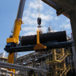
Case Study 1: Refinery Shell Side Fouling Removal
Hydrocarbon coking between baffle plates caused a 40 PSI increase in differential pressure in the shell side of a fixed tubesheet heat exchanger at a petroleum refinery. Water blasting was only capable of removing 35% the deposit. After introducing robotic jetting, a crew was able to reach 92% fouling in 18 hours of turnaround – returning the exchanger to within 5% of its original heat transfer coefficient. Water usage reduced to 5 GPM from 100 GPM, resulting in greater than 90% reduction in disposal costs.
92%
fouling removed
18 hrs
total cleaning time
95%
heat transfer recovery
Case Study 2: Chemical Plant Tube Bundle Cleaning
Severe tube side scaling from calcium carbonate deposits reduced heat transfer efficiency by an estimated 30%. Operating crews used automated multi-lance Hydroblasting at 15,000 PSI across a 500-tube bundle. With automated lancing, crews were able to clean 500 tubes in 6 hours – a task that took two operators 3 full days with manual lancing. Post-cleaning UT gauging verified 0-to-0 tube wall thinning. bundle cleaning allowed the heat exchanger to reach thermal capacity that was rated before; saving about one per cent of the cost of a new exchanger.
500 tubes
cleaned in 6 hours
75%
faster than manual
$180K
replacement avoided
Frequently Asked Questions

Q: How do you clean the shell side of a heat exchanger?
View Answer
Two methods cover large percentage of shell side cleanings. Clean-In-Place (or CIP) circulates a chemical solution through the shell to disintegrate deposits without removing the bundle – suggested for fixed tube sheet types. High-blasting (or HK) at 10,000-25,000 PSI targets for removable bundles on outside of tubes. Robot jetting system automatically moves the between baffles to expose fouling and take inspection reports on every tube at the same time.
Q: What is the best tube cleaning method for shell and tube heat exchangers?
View Answer
It all depends on type of deposit. Chemical cleaning is good with soluble scaling. Brushes or scrapers address average hard deposits. Hydroblasting at 10,000-40,000 PSI blows away some of the fouling. For large bundles with demanding turnaround schedules, automated multi-lance systems achieve fastest cleaning in lowest labor cost per tube.
Q: How long does it take to remove fouling from a heat exchanger?
View Answer
turnaround time depends on severity of fouling, size of exchanger, and method of cleaning selected. chemical circulates 4-24 hours. Manual tube side lancing takes a few hours for small bundles up to 2-3 days for large units. Automated multi-lance reduces it by 50-80%. shell side robotic jetting cleans most standard exchangers in 12-24 hours. Add extra time for bundle extraction, inspection, reassembly if a full pull is needed – it may take 1-2 days in large shell with tie rods and heavy flanges.
Q: What is the 10/13 rule for shell and tube?
View Answer
The 10/13 rule is a pressure design criterion for shell and tube heat exchangers. This rule requires that the design pressure of the lower-pressure side be greater than or equal to 10/13 (~ 77%) of the design pressure of the higher-pressure side. It comes from ASME hydrostatic test requirements where the test pressure is 130% of the design pressure (10/13 = 1/1.3).
The rule is to prevent the overpressure by tube rupture (when the pressured fluid from the high pressure side gets arbitrarily into the lower pressure side).
Q: Can you clean a fixed tubesheet exchanger without pulling the bundle?
View Answer
Yes, although such options are few and far between. Where possible, the tube side is cleaned mechanically – to do this the channel head is removed and the lances or brushes can be inserted through each of the tube. For the shell side, however, it is difficult – chemical circulation (CIP) is generally the first choice, wherein pumping cleaning solutions through the shell to dissolve deposits in place.
There are robot approaches for certain types of shell side where by the nozzle openings are accessed, however it depends largely on baffle spacing and foul severity. In fixed tubesheet heat exchangers with severe fouled conditions where CIP fails, the only option may be replacing the exchanger with a removable bundle design.
Q: What chemicals are used for heat exchanger cleaning?
View Answer
Typical cleaning chemicals use of hydrochloric acid(HCl) for mineral scaling and calcium deposits, NaOH for organic fouling and greasing, citric acid for light scaling on stainless steel (removes the risk of chloride corrosion), sulfuric acid as a HCl substitute for chloride sensitive tube, and special solvent for hydrocarbon or polymer deposits. Acid cleaning must always be accompanied with corrosion inhibitors to ensure taken tube surfaces gain protection in addition to neutralisation and passivisation of the cleaned metal.
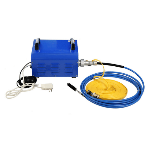
Need Shell Side or Tube Side Cleaning Equipment?
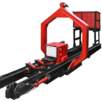
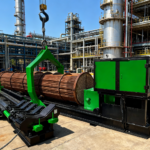
The BOSHIYA Group provides tube bundle pullers, tube side cleaners and shell side cleaning systems for petro refiners, chemical plants and power stations across the globe.
About This Guide
This article is written by the BOSHIYA Group maintenance engineering team based on field data from heat exchanger cleaning projects; involving petroleum refinery, petrochemical processing and power generation facilities. The comparisons of cleaning methods, pressure standards and turnaround times are based on documented project findings and officially published industry reseach; not any estimates. Since BOSHIYA manufacture and rent out tube bundle cleaning equipment, our point of view mainly focus on mechanically automated cleaning as long as the method has clear benefits.
References & Sources
- The Cost of Heat Exchanger Fouling in U.S. Industries — U.S. Department of Energy, Oak Ridge National Laboratory
- Estimating the Global Cost of Heat Exchanger Fouling — HeatX Global (Muller-Steinhagen analysis)
- Chemical Cleaning — Corrosion Control During Acid Cleaning of Heat Exchangers — ScienceDirect / Elsevier
- A World’s First in Fouling Removal (EU Horizon 2020 Research) — Energy Industries Council
- What Is Fouling in a Heat Exchanger? Causes, Detection & Prevention — CSI Designs
- Heat Exchanger Preventive Maintenance Checklist — FieldInsight
- Heat Exchanger Fouling Factor: Significance, Calculation & 2026 Standards — EPCLand
![ASME Pressure Vessel Fabrication Guide: Section VIII Requirements [2025]](https://boshiya.com/wp-content/uploads/2026/05/2-46-150x150.webp)