Get in Touch with BOSHIYA


Continuous Casting in Steelmaking: How the Process, Equipment, and Caster Selection Work
Contents
show
Continuous casting is the process that transforms molten steel directly into solid billets, blooms and slabs in a single uninterrupted strand, replacing the ingot route that dominated steelmaking before the 1950s. It now represents more than 90 % of the world’s crude steel — over 500 million tonnes a year, as quantified by the University of Illinois Continuous Casting Consortium — and defines the interface between liquid metal and every downstream rolling, forging and machining process in a modern steelmaking plant equipment line.
This guide is aimed at plant engineers, EPC procurement people and operators who are considering a new caster or retrofit; it discusses the seven-stage process, the major components, the forms of cast product, the implications against ingot casting, the materials which can be cast and a Caster Selection Matrix related to plant capacity. A brief future outlook section discusses the direction of the technology as steel moves toward decarbonisation.
Quick Specs
| Process Type | Strand casting (continuous solidification, steady-state) |
| Casting Speed (steel) | 1–8 m/min (billet up to 4 m/min, slab around 1.4 m/min) |
| Casting Speed (aluminium DC) | 0.03–0.1 m/min |
| Output Forms | Billet (<200 mm sq) · Bloom (>200×200 mm) · Slab (180–250 × 500–2200 mm) · Round (140–500 mm) · Strip (2–5 mm) |
| Mold Shell at Exit | 6–20 mm |
| Metallurgical Length | 10–40 m (steel curved caster) |
| Global Adoption | >90 % of crude steel · ~500 Mt/yr (steel) + 20 Mt (Al) + 1 Mt (Cu) |
| Reference Standards | ASTM A788, EN 10084, AISI/SAE grade specifications |
What Is Continuous Casting?
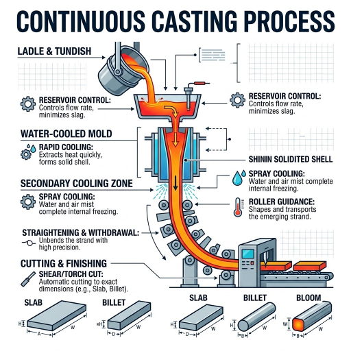
Continuous casting, also known as strand casting, is a steady-state process by which molten metal solidifies against a water-cooled mould while the partially solidified strand is withdrawn from the bottom of the mould at a matching rate. Liquid metal enters at the top while a solid section emerges at the bottom, and the run continues until the steel input is interrupted — typically a tundish-by-tundish sequence that can last anywhere from one hour to several weeks.
Continuous casting replaced the older route whereby molten steel was teemed into individual ingot moulds, kicked out, reheated in soaking pits and broken down through a primary rolling mill. Sir Henry Bessemer patented the working of casting between two counter-rotating rollers in 1857, but the major innovation to make it commercially active in the steel industry was Junghans’s 1934 invention of vertical mould oscillation with the “negative strip” principle, which prevents the solidifying shell from sticking onto the mould walls. Steel mills adopted the technology widely through the 1960s, and continuous casting surpassed the conventional ingot route in tonnage during the mid-1980s.
Today, continuous casting is the default route in almost every modern integrated mill and electric-arc-furnace mini-mill. Aluminium and copper are also continually cast, though the dominant aluminium format is a semi-continuous direct-chill (DC) machine as a continuous strand.
How Continuous Casting Works: From Ladle to Cut Strand
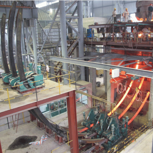
A modern steel caster operates as a fluid pipeline. Liquid metal enters the top of the machine in a teemed ladle, exits as a cooled strand at the bottom, and is cropped into manageable lengths — all while a downstream rolling mill schedules its own draft passes around the caster’s withdrawal rate.
Steel-caster flow runs through six physical stages:
- Ladle and turret — a teemed ladle sits on a rotating two-position turret directly above the caster. One ladle feeds the cast while the next is prepared “off-cast”, switched in when the first is empty. This handover is what gives continuous casting its name: the strand never stops while ladles change.
- Tundish — molten material flows through a refractory shroud into the tundish reservoir, lined with disposable tundish boards that can be easily replaced. This buffer evens out flow surges into each mould and lets oxide inclusions float into the slag layer for cleaner metal.
- Submerged entry nozzle (SEN) and mould — metal leaves the tundish through another refractory shroud and enters a water-cooled copper mould 0.5 to 2 metres deep. The copper mould oscillates vertically — or slightly off-vertical on a curved path — to keep the shell from sticking to the walls; a thin layer of mould powder melts on contact with the steel meniscus, lubricating the gap and trapping any remaining inclusions.
- Primary cooling and shell formation — inside the mould, a 6 to 20 mm shell quickly forms against the copper wall while the casting interior stays liquid. The strand exits the mould bottom into a spray chamber.
- Secondary cooling — water sprays and water-cooled rollers extract surface heat as the strand passes through the spray chamber. Rolls must be precisely aligned, as they also resist the ferrostatic pressure of the still-molten core.
- Straightening and cropping — on a curved-apron casting machine, straightening rollers bend the partially solid strand back to a horizontal axis. Once the casting has reached its metallurgical length (10 to 40 m for steel), the strand is cut into slabs, blooms, or billets by mechanical shears or oxyacetylene torches.
📐 Engineering Note
A modern steel caster runs at 1 to 8 m/min, with billet machines at the upper end (typically around 4 m/min) and conventional slab machines around 1.4 m/min. Casting speed is governed by the allowable liquid-core length: if the strand exits the mould before a sufficient shell forms, ferrostatic pressure causes a breakout. Withdrawal rate, mould water flow and spray-chamber cooling are coordinated by a programmable logic controller drawing on electromagnetic level sensors at the tundish and mould, plus thermal sensors along the strand path.
What Is the Step-by-Step Process of Continuous Casting?
A six-step sequence captures the shortest practical answer: tap molten steel into a ladle, transfer to a tundish above the caster, feed through a submerged entry nozzle into a water-cooled copper mould, allow primary solidification of the shell while the mould oscillates, withdraw the strand through secondary cooling sprays and support rolls, then straighten and cut to length. Each handover is buffered by the previous reservoir so the strand itself never stops moving while it is in steady state. Engineers at the University of Illinois Continuous Casting Consortium describe the steady-state condition as one in which the solid–liquid interface holds a constant position in the mould frame of reference, which is what distinguishes continuous casting processes from every other casting method.
Continuous Casting Machine: Key Components
Each station on a continuous casting machine carries a distinct technical role and a distinct service-life envelope. Plant audits and turnaround planning typically work down this list.
| Component | Function | Material / Service Life |
|---|---|---|
| Ladle & turret | Buffer between EAF/BOF and caster; supports handover | Refractory-lined; preheated before each cast |
| Tundish | Reservoir, flow regulator, inclusion separator | Disposable working lining (tundish boards) replaced per heat sequence |
| Submerged entry nozzle (SEN) | Delivers metal below the slag layer to prevent re-oxidation | Refractory ceramic; replaceable per sequence; alignment is a leading breakout cause |
| Copper mould | Primary heat extraction; forms the solid shell | Cr-plated copper plates: industry-reported 100–150 heats; Ni-plated: ~300 heats |
| Mould oscillator | Vertical oscillation prevents shell sticking (“negative strip” interval) | Hydraulic or mechanical drive; periodic inspection of bearings and stroke |
| Mould powder feed | Lubricates strand–mould gap; absorbs alumina inclusions | Synthetic flux specific to steel grade; consumable per cast |
| Secondary cooling spray | Water mist removes heat below mould exit | Nozzles map zone-by-zone to grade-specific cooling curves |
| Support & withdrawal rolls | Resist ferrostatic pressure; pull strand at casting speed | Closely spaced; alignment controls bulge and internal cracks |
| Straighteners & torch cutter | Bend strand to horizontal; cut to length | Hydraulic straightener rolls; oxyacetylene or plasma torch |
The mould copper plate is the highest-attrition component on a steel caster. Industry tracking from caster maintenance providers shows campaign life depends primarily on the coating: chromium-plated plates typically run 100–150 heats before reconditioning, while nickel-plated plates can reach roughly 300 heats. Replacement cost and lost tonnage during a mould swap are why coating selection and oscillation tuning carry capital-grade weight in plant operating budgets. Modern casters also use computational fluid dynamics on the tundish and mould to predict turbulence, slag entrapment and shell-thickness profiles before a steel grade is committed to a campaign. These integrated control systems and casting processes are now standard on tier-1 European and Asian plants.
To plan a complete equipment package — including matching the caster to upstream EAF or BOF capacity, refractory consumption and mould-yard logistics — you can configure your steel plant equipment with our steelmaking-line selector.
Cast Product Types: Billet, Bloom, Slab, Round, and Strip
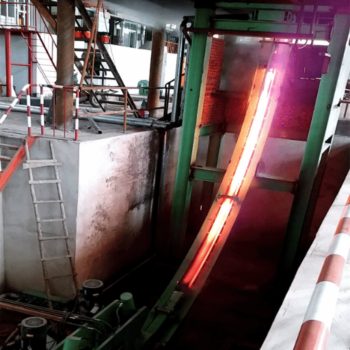
The caster is dimensioned around the section it casts, and the section is dictated by the downstream rolling mill. Five families dominate steel and metal plants worldwide.
| Cast Form | Typical Cross-Section | Length | Downstream Use |
|---|---|---|---|
| Billet | <200 mm square (typically 130–200 mm) | up to 12 m | Long products: rebar, wire rod, rails, angles, bars |
| Bloom | >200×200 mm, up to 400×600 mm | 4–10 m | Heavy sections, large bars, forging stock |
| Slab (conventional) | 100–1600 mm wide × 180–250 mm thick | up to 12 m | Hot-rolled coil, plate, automotive sheet |
| Slab (thin / wide / thick) | Thin 40–110 mm · Wide up to 3250×150 mm · Thick up to 2200×450 mm | up to 12 m | CSP-line hot strip; plate mill heavy plate |
| Round | 140 or 500 mm diameter | cut to order | Tube and pipe stock, ring rolling, large forgings |
| Beam blank | 1048×450 mm or 438×381 mm (I-beam profile) | cut to order | Direct rolling to structural I- and H-beams |
| Strip (direct cast) | 2–5 mm × 760–1330 mm | coil | Near-net-shape hot-rolled coil bypassing reheat |
Choosing the cast section is therefore choosing the rolling investment. Billet casters fit long-product mini-mills, slab casters fit hot-strip and plate mills, and beam-blank casters fit structural-section mills that would otherwise rely on heavy bloom-rolling chains.
Continuous Casting vs Ingot Casting: Why the Industry Switched
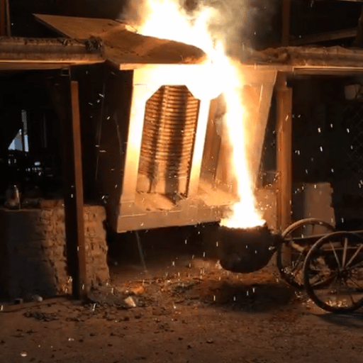
Before the 1960s, steel was teemed into stationary ingot moulds, demoulded after solidification, soaked in reheating pits and broken down on a primary rolling mill before reaching the finishing trains. Continuous casting eliminates the demoulding, soaking-pit and primary breakdown steps in one move — and that is the structural reason the industry switched.
✔ Advantages of Continuous Casting
- Higher metal yield: industry estimates indicate 95–96 % for continuous casting versus 84–88 % for ingot casting — roughly 7–12 % less metal lost as scrap.
- Lower energy per tonne: the U.S. Office of Technology Assessment estimated savings of about 2 MMBtu/tonne from yield gains alone, before counting eliminated reheating cycles.
- Steady-state quality: homogeneous solidification gives a more uniform microstructure than batch ingots.
- Throughput: a single multi-strand machine can replace a battery of ingot moulds plus the breakdown rolling chain.
- Automation-ready: PLC-controlled level, oscillation, and cooling enable consistent quality across long campaigns.
⚠ Limitations
- High capital cost: the caster and the associated upstream/downstream are multi hundreds of million dollars capex on integrated mill.
- Section flexibility : a billet caster is unlikely to switch to slab and Vice-Versa , a steel casters is unlikely to switch to aluminium.
- Breakout risk: a shell rupture below the mould can cost $200,000 to several million dollars per incident, depending on damage.
- Tooling wear: oscillating mould and water-cooled rolls require continuous maintenance.
- Steady supply requirement: the upstream EAF/BOF must deliver a consistent temperature window or turnarounds become frequent.
Does Continuous Casting Make Better Steel and More of It?
On both counts, yes – but with caveats. On output, continuous casting’s homogenous solidification reduces down grades-due to rejections of association-moulding head and tail crops by more saleable steel produced per unit mass. On quality, steady-state cooling initially produces a more uniform as-cast microstructure than the variable cooling of stationary ingots does, and the SEN-and-mould-powder process removes inclusions more reliably than open ingot teeming does. Both gains depend on tight process control — a poorly tuned caster with frequent breakouts, mould-flux entrapment or level fluctuations can yield steel that is no better than a well-run ingot shop. Industry sources commonly report that the actual quality premium becomes visible only when the caster runs at design temperature window with computational-fluid-dynamics-tuned tundish flow.
Materials Cast Continuously: Steel, Aluminium, Copper, and Beyond
Although steel dominates by tonnage, the continuous casting principle extends across every base metal. The University of Illinois CCC quantifies the global picture at roughly 500 million tonnes of steel, 20 million tonnes of aluminium and one million tonnes of copper, nickel and other metals continuously cast each year.
| Material | Caster Variant | Typical Casting Speed | Typical Output |
|---|---|---|---|
| Steel | Curved-apron (most common); vertical for specialty alloys; thin-slab CSP; twin-roll Castrip | 1–8 m/min | Billet, bloom, slab, beam blank, strip |
| Aluminium | Direct-chill (DC) or electromagnetic (EM) — semi-continuous; twin-belt for strip | 0.03–0.1 m/min (DC); up to 14 m/min (twin-belt strip) | Round ingot 50–500 mm dia; strip 10–35 mm × ≤2035 mm |
| Copper & copper alloys | Twin-belt or vertical/horizontal; upcasting for high-purity wire stock | up to 14 m/min (twin-belt) | Bar 35–75 mm × 50–150 mm; anode plate; rod for wire drawing |
| Brass / bronze | Horizontal continuous casting | Lower than steel — alloy-dependent | Bar, tube, profile |
| Nickel / superalloys | Electroslag remelting (ESR); vacuum arc remelting (VAR) | Slow, batch-like | Round sections up to 1.5 m diameter for aerospace |
The common principle that connects these variants is a solid-liquid interface that advances at a constant position; the variation is in the mould geometry, withdrawal velocity and any atmosphere control. Aluminium DC casting melts a much smaller metallurgical length (0.1-1.0 m) than steel because the lower casting temperature together with the higher heat conductivity enable the strand to be cooled more rapidly.
Caster Selection: Configuration, Strands, and Plant Capacity

For a new plant, or a facelift of an existing site, the decision for caster choice is three-fold: section family (billet/bloom/slab and round), strand quantity and machine geometry (horizontal, inclined or vertical). Strand number and section type define the capacity, the machine geometry the building height, capex, and achievable steel type. A capacity-to-configuration table below maps the most commonly procured option at each scale.
📐 Caster Selection Matrix by Steel Plant Capacity
| Plant Capacity (Mt/yr) | Recommended Caster | Strands × Section | Typical Radius |
|---|---|---|---|
| < 0.5 Mt | Curved single-strand billet caster | 1× billet 100–150 mm sq | R6 m |
| 0.5–1.5 Mt | Curved 4-strand billet/bloom caster | 4× billet 130–200 mm sq | R6–R8 m |
| 1.5–4 Mt | Curved 6-strand billet OR single-strand slab | 6× billet 130–200 mm sq · or 1× slab 1200–2200 mm wide | R8–R10 m |
| > 4 Mt | Twin-strand slab (or slab + bloom dual line) | 1–2× slab 1800–2500 mm wide | R9–R11 m |
The column in the table marked radius is more important than it appears: a larger radius provides for a section of greater thickness without causing damaging unbending strain on the forming strand, but it also increases the building height, the amounts of refractory stock and the crane span. To some extent most billet-and-bloom plants settle at R6 to R10 m. Vertical machines behave with no unbending bent for just the category of grade that is not manageable on even a curved layout, for example, heavy stainless steel, some superalloy rounds, or most tool-grade steel.
Once the section and strands are chosen, downstream rolling, refractory consumption and the upstream EAF or BOF ladle cycle must all balance the caster’s withdrawal rate. To put preliminary investment numbers around a configuration, you can estimate steel plant capex with our cost-modelling tool, or our complete steel plant package documents the integrated EAF–LF–caster–rolling-mill scope.
What Is the Difference Between Centrifugal and Continuous Casting?
Centrifugal and continuous casting are two distinct families. In continuous casting, the strand is solid in cross-section and indefinite in length — produced by withdrawing a solidifying strand from an open-ended mould. In centrifugal casting, the strand is hollow and finite in length — produced by pouring molten metal into a horizontally rotating cylindrical mould, where centrifugal force pushes the melt against the mould walls to form a cylindrical hollow casting. Centrifugal is the route for individual cast pipes, large-diameter cylinders and ring segments. Continuous casting cannot produce hollow cross-sections of arbitrary diameter in a single operation, and centrifugal casting cannot produce extended rectangular billets, blooms or slabs. These two are complementary, not competing, processes.
Industries and Global Production: Where Continuous-Cast Steel Goes
Global crude steel production reached approximately 1.83 billion tonnes in 2024 according to worldsteel-aligned reporting, a slight year-on-year decline. With more than 90 % of that volume cast continuously, the technology underpins nearly every downstream metal-product industry. Long products (rebar, wire rod, sections) supply construction, civil infrastructure and the energy-grid expansion now driving demand growth in Asia and the Middle East. Flat products (hot-rolled coil, plate) supply the automotive, line-pipe, shipbuilding and white-goods industries. Specialty rounds and superalloy continuous-cast or remelted billets supply aerospace turbine and chemical-process applications. In that sense, continuous casting acts as the last neutral interface between steelmaking and the world’s downstream metal demand. For project-scale delivery on EAF–caster integration, our EPC services for steel plants page covers our turnkey scope.
Industry Outlook: Near-Net-Shape, Strip Casting, and Green Steel
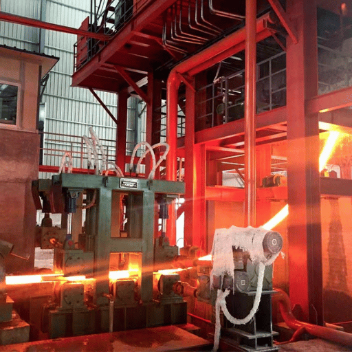
The mature continuous casting process is evolving along three vectors that will matter to new equipment deals authorized 2026-30.
- Near-net-shape thin-strip casting — twin-roll Castrip technology, deployed by Nucor in the United States, casts 2-mm sheet directly from molten steel and bypasses much of the conventional reheating and roughing chain. Arvedi’s Endless Strip Production (ESP) line at Cremona, Italy — running since 2009 with capacity above 2 million tonnes per year — produces hot-rolled coil from liquid steel in roughly eight minutes and reports about 45 % energy savings versus conventional CSP. Both are commercial today, but they remain a single-digit share of global hot-strip output. The 2025 LeadIT green-steel project review found that the bottleneck is not the casting technology itself; it is the broader investment cycle, regulatory uncertainty, and the difficulty of integrating new casters into legacy hot-strip mill footprints.
- Hydrogen-DRI integration — direct-reduced iron produced with hydrogen rather than natural gas can feed an electric-arc furnace whose liquid steel is cast on a conventional curved caster, meaning the caster need not change but the upstream hot-metal mix and steel chemistry will. thyssenkrupp’s Duisburg site, supplied by SMS group and Midrex, is the leading European reference for a hydrogen-ready DRI plant feeding open-bath furnaces ahead of an existing slab caster.
- Digital-twin process control — computational fluid dynamics is moving from the design office into live-mould level-control and tundish-flow optimisation, with breakout-prediction systems already commercial on multiple European and Chinese casters.
If you are planning a new steel plant or retrofitting an existing line for 2026–2030 commissioning, the implication is conservative: the curved caster you procure today will likely outlive at least one upstream-feedstock change (DRI replacing scrap or BF hot metal), so optionality at the ladle metallurgy and tundish refractory level matters more than betting on a specific strip-casting variant. Our technical service for caster retrofits team supports refractory upgrades, mould-flux trials, and oscillation tuning during these transitions.
FAQ
Q: What is the difference between direct chill and continuous casting?
View Answer
Direct chill (DC) casting is the dominant aluminium variant. A water-cooled mould — similar to the steel version — supports a strand on a hydraulic platen that lowers into a casting pit, so the cast eventually stops when the platen reaches the floor. True continuous casting (the steel form) runs indefinitely while the strand is withdrawn through rolls below the mould. DC is therefore semi-continuous: long enough to deliver a clean ingot but bounded by pit depth.
Q: When was continuous casting invented?
View Answer
Sir Henry Bessemer patented the principle of casting metal between two counter-rotating rollers in 1857. Junghans’s 1934 mould oscillation patent with the “negative strip” concept made it commercially workable for steel, and steel mills adopted the curved-apron form widely through the 1960s.
Q: How much does a continuous casting machine cost?
View Answer
Continuous casting machine capex varies far too widely for a useful single figure: a single-strand R6 m billet caster for a small mini-mill is in a different order of magnitude from a twin-strand slab caster on a four-million-tonne integrated mill. Useful budgeting starts not with the caster line item but with the full steelmaking-and-rolling chain — EAF or BOF, ladle metallurgy, caster, and matching rolling mill — because a caster procured to the wrong section family forces costly downstream rework. Request a per-project quotation that holds caster capex against ladle cycle, refractory consumption, and rolling-mill throughput rather than a generic per-tonne figure.
Q: What metals can be cast continuously besides steel?
View Answer
Aluminium (the largest non-ferrous user, mostly via direct-chill or electromagnetic semi-continuous casting), copper and copper alloys (rod, bar, anode plate via twin-belt or horizontal continuous casting), brass, bronze, lead, zinc, and nickel-based superalloys (typically via electroslag remelting or vacuum arc remelting). Steel still dominates by tonnage at roughly 500 Mt/year against 20 Mt aluminium and 1 Mt for everything else.
Q: Is continuous casting cheaper than sand casting?
View Answer
Per tonne of indefinite-length 2D section at high volume, yes — clearly. For one-off complex 3D parts, sand casting wins because continuous casting cannot produce them at all.
Plan Your Caster — Talk to Our Engineering Team
Boshiya engineers integrated steelmaking and metal-plant equipment lines including continuous casters, ladle metallurgy, electric-arc furnaces, and rolling-mill packages on an EPC basis. If you are scoping a new plant, retrofitting an existing caster, or evaluating a section-mix change for a downstream rolling line, get specifications and lead times tied to your throughput and grade target.
Talk to a Boshiya engineer about your caster project →
About This Analysis
This document assembles all published equipment specifications, scholarly process figures, and industry-association training publications for continuous casting. Service-life values for mould copper plates and breakout incident-cost thresholds are derived from third-party industry reporting, and will require tuning to your specific steel grade, casting speed, and mould-flux choice. We have not referenced proprietary first-party plant figures in this article; ask for a per-case configuration analysis specific to your steel grade and section family.
References & Sources
- Introduction to Continuous Casting — University of Illinois Continuous Casting Consortium (CCC)
- World Steel in Figures 2025 — World Steel Association
- Continuous Casting — A Practical Training Seminar — Association for Iron & Steel Technology (AIST)
- Arvedi ESP Line Starts Endless Strip Production — Association for Iron & Steel Technology
- Benefits of Increased Use of Continuous Casting by the U.S. Steel Industry — U.S. Office of Technology Assessment
- Casting — Industrial Efficiency Technology & Measures — Institute for Industrial Productivity / U.S. EPA
- 2025: a year in review for green steel — LeadIT (Industry Transition)
- Pathways to Green Steel — Midrex Technologies
Related Articles
- Steel and Metal Plants — Equipment & EPC overview — full plant scope including continuous casters
- Steel Plant Configuration Selector — match EAF, ladle, caster, and rolling mill to your capacity
- Steel Plant Cost Estimator — preliminary capex modelling for integrated steel plants
- Equipment Rental for Caster Outages — refractory replacement and turnaround support
- Infrastructure Equipment — supporting industrial systems for steel plants
![Polypropylene Resin: Grades, Types & Selection Guide [2026]](https://boshiya.com/wp-content/uploads/2026/05/0-150x150.webp)