BOSHIYAと連絡を取りましょう


接触分解の 3 つの主なタイプは、固定床、移動床、流動床プロセスです。現代の製油所の議論では、従来の流動接触分解 (FCC)、残留物 FCC (RFCC)、および深部接触分解 (DCC) などの製品指向の技術も区別されています。これらのラベルには、触媒の移動、供給原料または所望の製品混合物の適合性など、さまざまなことが記載されています。
内容
ショー
したがって、残留物変換の提案には、RFCC という文字よりも詳しく説明する必要があります。供給原料、触媒冷却、ガス回収能力に含まれる汚染物質により、装置の範囲が変更される可能性があります。この文書では、非水素付加接触分解について説明します。水素化分解は水素を添加し、別の製油所ルートの一部です。
一目でわかる触媒亀裂の種類
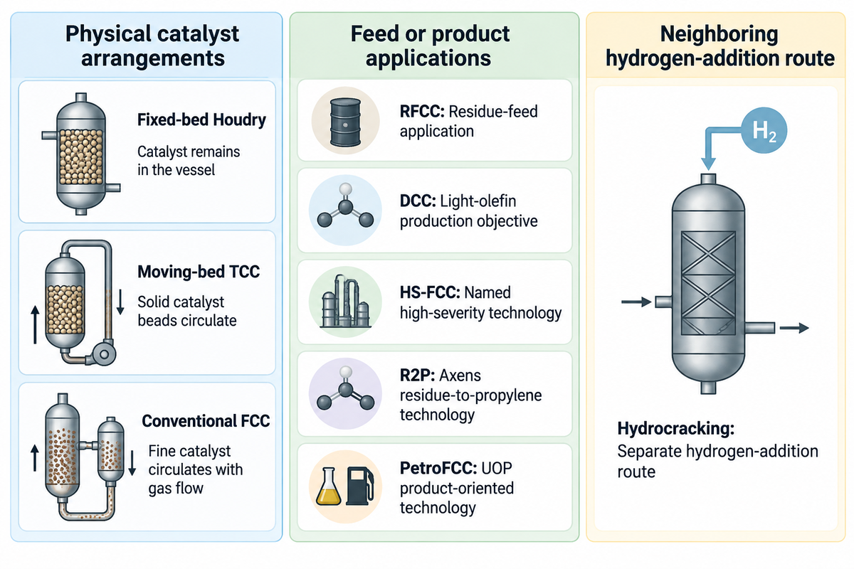
触媒分解プロセスは、触媒の動きと、変換または生成されるものに基づいて区別できます。固定床、移動床、流動床は物理的配置を表します。 RFCC と DCC は、流体触媒プロセスのより広範なファミリー内でのアプリケーションまたは名前付きテクノロジーを説明するため、追加の床カテゴリーではありません。
二軸クラッカーマップ
2 軸クラッカー マップは、触媒の配置をフィードおよび製品の目的から分離し、購入者がテクノロジー オファーを分類できるようにします。
| ラベル | 分類レベル | 買い手に伝えること | まだ定義が必要なのは |
|---|---|---|---|
| 固定ベッド Houdry | 原子炉配置 | 触媒は容器内に残ります | スイングシーケンスと熱供給 |
| 可動ベッド TCC | 原子炉配置 | 固体触媒ビーズが循環します | 輸送および再生レイアウト |
| 従来のfcc | 流動触媒配置 | 細かい触媒はガス流とともに循環します | 飼料アッセイと製品ベース |
| RFCC | 残留物供給アプリケーション | FCC はより重い残留飼料に適応しました | 金属の許容範囲と熱バランス |
| DCC | Sinopec 製品指向テクノロジー | ライトオレフィン製造の目標 | 名前付きバリアントと製品回復 |
| HS-FCC | ハイシーバリティ技術と名付けられました | 接触時間が短いダウンフロー反応 | 飼料の品質と統合された回復 |
| R2P | Axens の残留物からプロピレンへの技術 | 残留飼料とプロピレンの対物レンズ | Residue properties and added equipment |
| PetroFCC | UOP product-oriented technology | FCC features aimed at light olefins or aromatics | Selected process features and feed |
| 水素化分解 | Separate hydrogen-addition route | Cracking with hydrogen and catalysts | Hydrogen supply and product slate |
Penn State’s Houdry description anchors the historical distinction of beds. Modern terms followed the relevant licensors’ terminology. For procurement, specify both the reactor arrangement and the feed and product objectives in the scope; a process name alone leaves the heat-recovery requirements undefined.
固定床および可動床の触媒亀裂
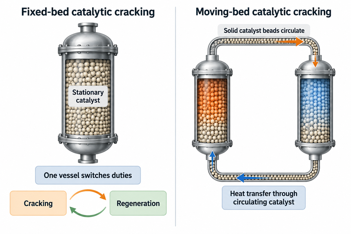
Fixed-bed catalytic cracking holds the catalyst stationary and switches between cracking and regeneration for each catalytic reactor. Moving-bed cracking circulates solid catalyst. Hot catalyst circulation supplies heat for the cracking reaction. However, the mechanical transport arrangement would affect heat loss and the complexity of the plant.
固定ベッドは連続的な植物の出力を支えることができます
Penn State exemplifies the Houdry process using three parallel reactors. In the historical example, gas oil enters a catalyst-packed vessel at 800°F, and coke deposits progressively reduce catalyst activity. After about 10 minutes of cracking, feed is switched to another reactor so the plant can continue processing oil.
In this historical example, the vessel undergoes five minutes of steam stripping to remove residual hydrocarbons from the catalyst, followed by about five minutes of catalyst regeneration to burn off coke. These steps explain the cyclic nature of one reactor while the wider installation can provide continuous output. The third reactor provides some allowance for delays in returning a vessel to cracking duty.
移動床接触分解とは何ですか?
Moving-bed catalytic cracking circulates solid catalyst beads between the two duties. In the historical Thermofor Catalytic Cracking process (TCC), movement of catalyst carries heat between the two duties. TCC is a catalytic process; its name does not make it thermal cracking.
Penn State’s moving-bed explanation covers bucket-elevator and gravity flow transport. The drawback of these historical systems was heat loss during transport. These historical systems show the development of modern cracking, but the mechanical arrangements of the systems shouldn’t be assumed to represent a current fluid-catalyst offer.
流体触媒亀裂: 現代の基本プロセス
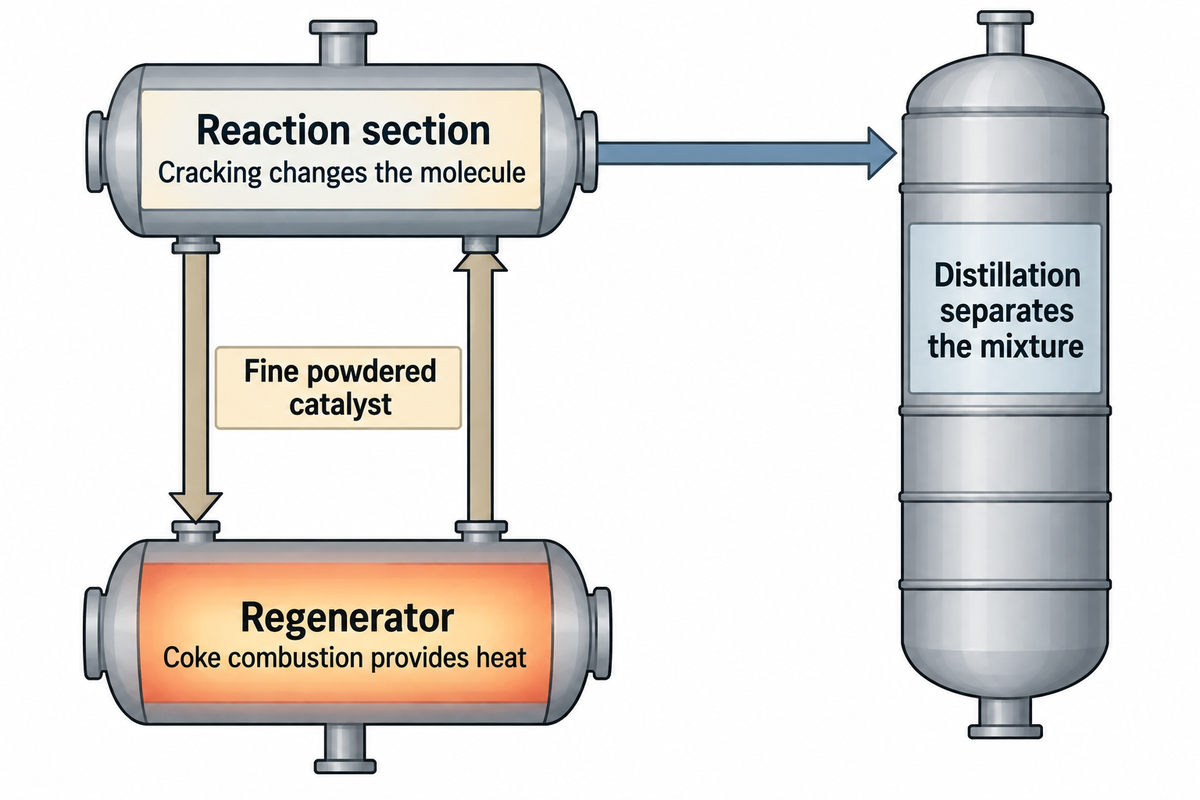
Fluid catalytic cracking passes a fine powdered catalyst between a reaction section and a regenerator. Gas flow makes the particles behave as a fluid and allows catalyst transport and rapid mixing with vaporized feed. Combustion of coke restores available catalyst surface and provides heat for the breakdown of large hydrocarbons into lighter products, including gasoline components.
“The coke on the spent catalyst is burned off, which reheats the catalyst to add heat to the FCC process.”
In a fluid catalytic cracker, regenerated catalyst comes back to contact the feed. Cracking changes the hydrocarbon molecule; the downstream fractionating column separates the mixture by distillation. The gasoline, gas, and cycle oil streams have different end points, and a cycle oil fraction may require further treatment to be used as diesel fuel.
Vacuum gas oil is a common FCC feedstock obtained after crude oil separation. In Penn State’s illustrative FCC description, the gas oil feed is preheated to about 300 degrees Fahrenheit and introduced into the reactor with steam. The chemical reaction and the separation train perform different functions: more reaction conversion can increase the load on downstream equipment. For more details on the reactor, regenerator and product streams, see our FCC process fundamentals.
This catalyst behavior is called fluid bed catalytic cracking. In Speight’s FCC overview, the finely powdered catalyst has a particle size on the order of 70μm and behaves like a fluid when mixed with the vaporized feed. Different internal flow patterns occur within vessels, and not all fluidized-solids processes use a catalyst.
RFCC: FCC を残留飼料に適応させる
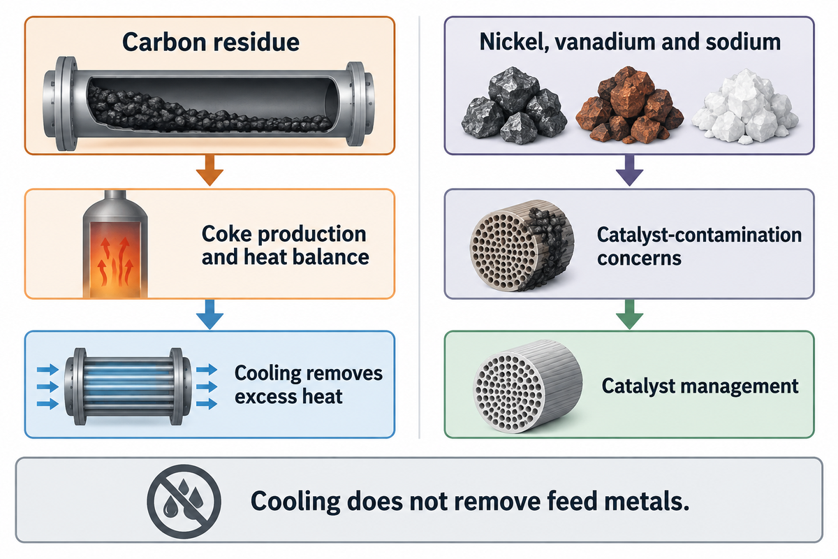
RFCC adapts fluid catalytic cracking to a residual feed that can increase the demands placed on catalyst management and regenerator heat removal. Carbon residue and feed metals are separate screening variables. A workable design must address carbon residue and feed metals, along with the required products.
UOP’s FCC-related processes datasheet targets its RFCC process at residual feeds above 4 wt% Conradson carbon. The datasheet describes a two-stage regenerator with catalyst cooling as the usual arrangement to manage the additional coke and heat.
Axens’ catalytic cracking overview uses different design context: single-stage regeneration is generally adequate for traditional distillate feeds or blends below roughly 2–3 wt% carbon residue, while residues above 3 wt% with high metals require more elaborate designs. These descriptions address their respective feed and technology ranges.
- Carbon residue: identifies a feed tendency relevant to coke production and the heat balance.
- Nickel, vanadium and sodium: add catalyst-contamination concerns that carbon residue doesn’t describe.
- Catalyst condition: affects the available activity and the management strategy for continued residue processing.
Cooling removes excess heat; it doesn’t remove feed metals. Proposals for heavier-feed flexibility require feed assay data and a catalyst management plan alongside the cooler load. The detail for formulation choices will be found in a different document on FCC catalyst composition and selection.
DCC および高プロピレン FCC: 製品指向の構成
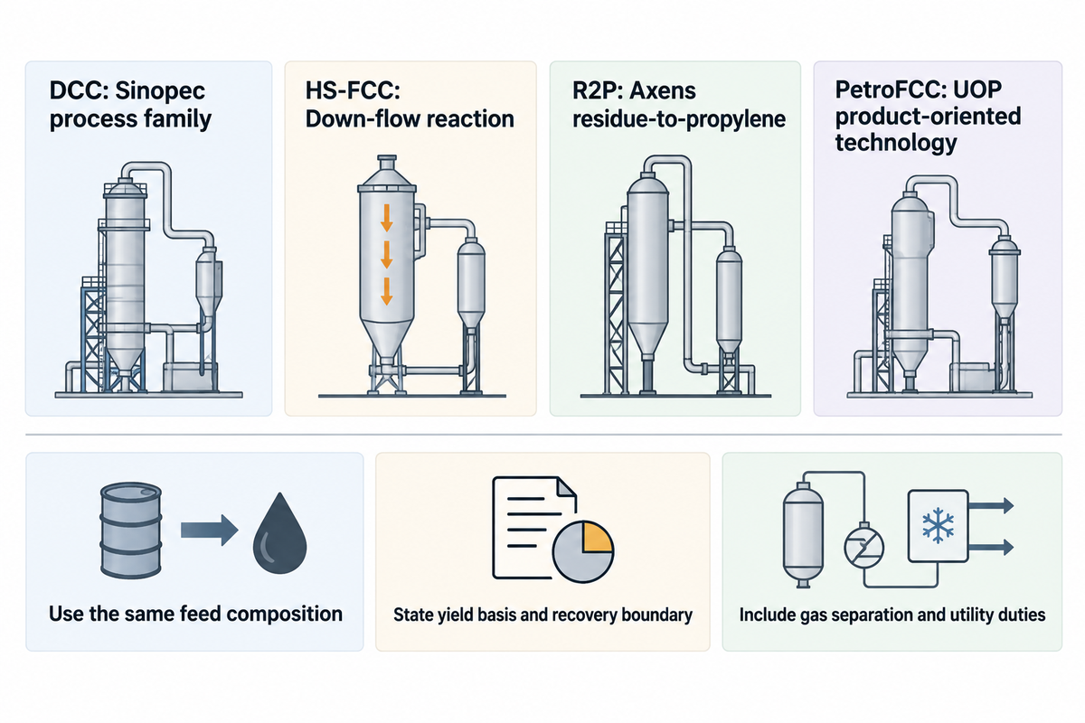
DCC technologies and other high-propylene FCC processes shift the product focus to light olefins. However, they retain distinct process identities. DCC is a Sinopec process family. Other licensors offer configurations for higher propylene product targets, so a comparison should be made with respect to feed, reaction design and product recovery rather than with the DCC process name in isolation.
In their presentation on DCC technology, Sinopec engineers Zhu and Shou describe the DCC platform and integrated variations. Proposers should verify the variant of the DCC technology offered as well as the recovery package, especially if the objective is to produce chemical products as opposed to a gasoline-led refinery slate.
Technip Energies’ HS-FCC description combines high temperature with down-flow reaction, short contact time and high catalyst circulation. Short contact time limits secondary reactions, while catalyst circulation provides heat and active surface for cracking. Axens names R2P for residue-to-propylene service, while UOP describes PetroFCC features aimed at light olefins or aromatics.
Relabeling all the processes as DCC conceals the differences in reactor design, feed, and licensing scope.
Compare
- Use the same feed composition.
- State the yield basis and recovery boundary.
- Include gas separation and utility duties.
Avoid
- Substituting one licensed name for another.
- Treating reactor yield as shipped product.
- Assuming severity changes need no hardware.
For the plant manager, the important consideration is how much on-spec propylene is available at the recovery outlet. For finance, that same limit sets the boundary of what separation equipment should be captured in the capital estimate. A higher rate of cracking is useful only within the limits of the complete system, including capacity and product quality.
FCC バリアント全体の熱回収とボトルネック
FCC variants can cause a shift in the limiting duty among regenerator, gas recovery, fractionation and heat exchangers. A higher propylene target creates different questions from a higher residue feed. Each proposed change should be connected to the affected system and its capacity evidence before a reactor modification is the basis for the project budget.
プロセス変更によるボトルネック比較
| Proposed change or symptom | System to compare | Required project input | Lead discipline |
|---|---|---|---|
| Higher residue carbon | Regenerator and catalyst cooler | Coke/heat balance and cooling duty | Process licensor |
| More feed metals | Catalyst management | Feed assay and catalyst condition | Process and catalyst specialists |
| More wet gas | Wet gas compressor | Gas rate, pressure and driver capacity | Process and rotating equipment |
| More recoverable propylene | Gas concentration and fractionation | Product specification and recovery basis | Process engineering |
| Higher unit throughput | Main fractionator | Vapor/liquid loads and pressure loss | Process and column specialists |
| Lost slurry heat recovery | Slurry exchangers | Duty, pressure-drop and fouling history | Heat-transfer and maintenance teams |
| Added catalyst cooling | Steam generation and users | Steam pressure and utility balance | Process and utilities teams |
| Changed coke combustion | Air supply and flue-gas system | Integrated pressure and flow balance | Process and environmental teams |
| Additional recovery equipment | Offsites and tie-ins | Utility capacity, plot space and outage scope | Project engineering |
As noted in the Axens propylene discussion, there can be hydraulic constraints which drive throughput to lower levels. The UOP catalyst cooler can generate either medium- or high-pressure saturated steam, while liquid product heat recovery is accomplished using slurry exchangers. Flue gas heat recovery and carbon monoxide handling are part of a different circuit, and these duties shouldn’t share one generic exchanger specification.
イン Gary Martin’s 2016 revamp example, increasing feed from 33,500 to 40,000 b/d and conversion from 78.5 to 81.8 vol% is described. The wet gas compressor is driver-limited in this example. Conducting an isolated reactor-capacity study would leave a major constraint unaddressed downstream.
Martin assesses the integrated pressure system, consisting of the air blower, regenerator, fractionator and compressor. The case presents an interesting budgeting lesson. Retained equipment can determine the feasible expansion, even if the reaction section has headroom for changes. Therefore, procurement should request the bottleneck basis with the proposed scope and finance should evaluate alternatives on the basis of the same throughput and conversion assumptions.
石油分解ルート: 触媒および熱分解
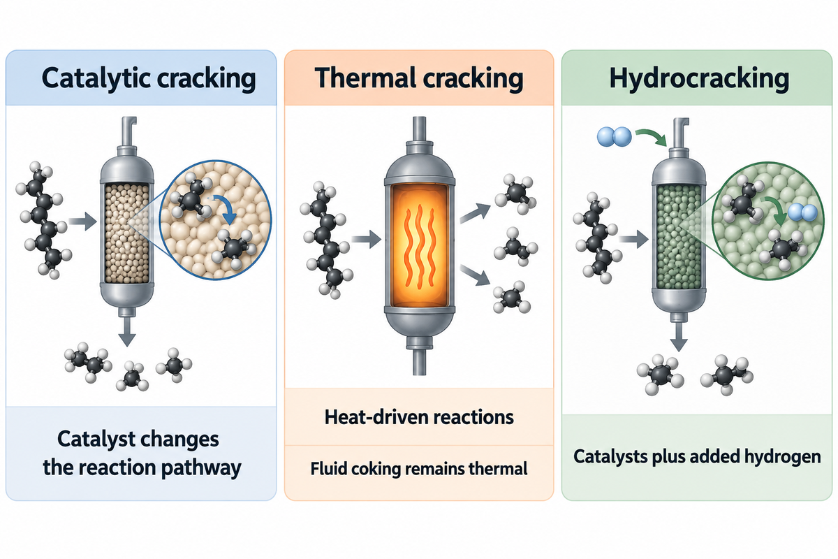
Catalytic cracking and thermal cracking employ different reaction routes to convert heavier hydrocarbon feed to smaller molecules. Catalytic cracking uses a catalyst without the hydrogen-addition scheme of hydrocracking. Thermal routes depend on heat-driven reactions, and therefore their product objectives should be evaluated separately compared to FCC catalyst-bed arrangements.
接触分解と熱分解の違いは何ですか?
Catalytic cracking uses a catalyst to alter a reaction pathway and product selectivity, while a thermal cracking process relies on heat without that catalytic function. The reaction chemistry and differences are explained in Penn State’s conversion-process overview. Both can break larger molecules into smaller molecules; however, the feed and desired products determine which refining process is applicable to the project.
Catalytic routes
- FCC circulates fine catalyst.
- RFCC addresses residual-feed requirements.
- Hydrocracking adds hydrogen and has separate process requirements.
Thermal routes
- Steam cracking targets petrochemical olefins.
- Coking converts heavy feeds and produces coke.
- Fluid coking uses fluidized solids without becoming FCC.
の The EIA’s refining definitions distinguish fluid coking from catalytic cracking, and describe the hydrogen requirement of the hydrocracking process. For an olefin project utilizing lighter feed, see the naphtha steam cracking guide. For hydrogen-based upgrading, see hydrocracking and hydrotreating. A kerosene, distillate or fuel oil objective calls for a completely different product comparison from an objective centered around gasoline and propylene.
テクノロジー ライセンサー、機器サプライヤー、および範囲の見直し
A refining technology licensor defines the licensed process basis. Engineering contractors integrate the project. Equipment and maintenance suppliers deliver their scopes. The cost to revamp an FCC unit follows these boundaries. Two quotations can differ in retained equipment, utility changes and outage work while appearing to promise the same feed capacity or product target.
Ed Palmer’s front-end scope discussion relates revamp planning to equipment condition, offsites and utilities. Comparing only reactor package prices leaves other project costs outside the scope of the decision.
価格を比較する前に成果物を分けてください
| Work package | Include in the comparison | Primary interface |
|---|---|---|
| Process technology | Named process, feed range and product basis | Licensor and refinery owner |
| Retained equipment | Capacity assessment and required modifications | Engineering contractor |
| Gas recovery | Compression, separation and product specification | Process and equipment teams |
| Heat exchangers | Thermal duty, materials and mechanical scope | Designer and manufacturer |
| Utilities and tie-ins | Steam, cooling and connection requirements | Site project team |
| メンテナンスアクセス | Bundle dimensions, weight and removal space | Maintenance equipment supplier |
In its 2022 investigation release, the U.S. Chemical Safety Board noted that portions of many older U.S. FCC units had been revamped by multiple technology licensors. Trace the design history of each affected section before assigning new work; the original process name may not describe every subsequent modification.
For a refinery owner deciding how to refine a heavier feed, a good commercial comparison is a common scope with exclusions visible. Equipment with a lower price can still require more site work.
メンテナンス インターフェイスとプロジェクトのハンドオフ
Maintenance handoff connects the process duty to the physical exchanger and the equipment to service it. Thermal performance and tube-bundle dimensions and access are additional inputs. A supplier can select handling or cleaning equipment only when the project inputs match the actual exchanger, rather than a general label such as RFCC or cat cracker.
に a 2008 article by Grace engineers David Hunt, Bill Minyard and Jeff Koebel, one refiner needed three slurry-exchanger cleanings within ten weeks. Each cleaning caused a feed-rate reduction. The authors present the interrelation between heat-transfer duty and the exchanger’s operating history with regard to fouling.
The inquiry for the cleaning equipment needs to address the deposit condition and access arrangement. Process engineers assess why deposits formed and quantify the lost heat-recovery duty. Bundle handling covers mechanical removal of the tube bundle. The reported case wasn’t simply about the cost of the cleaning equipment. The production loss was due to repeated loss of exchanger availability.
The public scope sheet for API 660 lists mechanical design, material selection, fabrication, inspection and testing requirements for specified shell-and-tube heat exchangers used in petroleum refining. The project requirements must still define the service and equipment type.
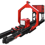
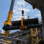
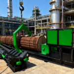
Sinopec’s DCC offering and the process technologies of UOP and Axens involve process licensing. At BOSHIYA, our focus is on tube-bundle handling and cleaning equipment, rental and service support. When requesting tube bundle extraction equipment そして exchanger cleaning equipment for the planned outage, please send us the dimensions, weight of the bundle and deposit condition, access constraints and your planned service scope.
Maintenance handoff
Carry the actual exchanger duty and access requirements into the maintenance package.
私たちの refinery equipment services address the maintenance scope through handling and cleaning equipment rental and service support.
よくある質問frequently Asked Questions
石油精製における3 種類のクラッキングとは?
このガイドでは、熱分解、接触分解、水素分解を 3 つの反応経路として比較します。水素分解では触媒も使用し、水素が追加されてプロセス要件が区別されます。非水素添加接触分解では、歴史的な反応器の分類は固定床、移動床、流動床です。流体コーキングはその違いを示しています。流動固体を使用しますが、熱プロセスのままです。
割れの主な2 つの種類は何ですか?
広い区別は熱分解と接触分解です。熱は前者を駆動し、触媒は後者の反応化学を変化させます。水素分解では水素が追加され、通常、そのプロセス要件により個別に議論されます。固定床、移動床、流動床は代わりに触媒の配置を記述するため、これらのラベルは別の分類の質問に答えます。
接触分解にはどの触媒が使用されますか?
最新の FCC は、ゼオライト活性成分と支持マトリックスを含む微細な触媒粒子を使用しています。新鮮な触媒の補充と日常的なコークスの除去は、触媒状態のさまざまな側面に対処します。コークスの除去により利用可能な活性表面が回復しますが、汚染物質の蓄積には個別の管理が必要です。配合を選択するには、プロセスの頭字語だけでなく、飼料と製品の目的も必要です。
水素化分解は接触分解の一種ですか?
水素分解は化学的な意味で触媒作用を及ぼしますが、石油業界の分類では、添加された水素を使用するため、一般に別のプロセスとして扱われます。したがって、このガイドでは、主要な FCC ファミリー分類法の外にある、隣接するルートとして比較します。
RFCCとDCCは交換可能ですか?
No. RFCC describes residue-feed processing within the fluid-catalyst family, while DCC identifies a particular technology family directed toward light olefins. A residue-processing project may also target propylene, but that combination still requires a named process design, feed basis and recovery scope. Compare the catalyst and heat-management requirements, then the downstream gas and product-recovery duties. Shared use of a fluidized catalyst doesn’t make the reactor internals, regeneration arrangement or product guarantees interchangeable. The technology licensor’s defined scope determines what’s included in an actual offer.
参考文献と情報源
- Penn State: Houdry catalytic cracking.
- Penn State: Moving-bed catalytic cracking.
- U.S. EIA: Fluid catalytic cracking process explanation, 2012.
- Gary Martin: FCC unit revamps at minimum cost, 2016.
- Penn State: Catalytic conversion processes overview.
- U.S. EIA: Refinery process definitions.
- Ed Palmer: Accurate front-end scope definition, 2014.
- U.S. Chemical Safety Board: Husky Superior investigation release, 2022.
- Hunt, Minyard and Koebel: Minimising FCC slurry exchanger fouling, 2008.
- American Petroleum Institute: API 660 public scope sheet.