BOSHIYAと連絡を取りましょう


Direct reduced iron (DRI) is produced by converting iron ore to metallic iron through solid-state reduction below iron’s 1,538 °C melting point. Mills assessing demand for direct reduced iron need to qualify lower-residual feedstock for the electric furnaces used to melt automotive and flat rolled steels. For engineers assessing a DRI purchase or production process across iron and steelmaking, the practical starting points are feedstock qualification, 、 ザ DRI-to-EAF charge balance, 、 および process-gas equipment requirements; the cost of the steel being produced depends on gangue chemistry, carbon, discharge temperature and heat-exchanger reliability.
内容
ショー
エンジニアリングパラメーターを一目で確認できます
- Process window: Solid-state reduction of iron oxides to metallic iron at temperatures below the melting point of iron without melting.
- Dominant routes: Gas-based vertical shaft furnaces vs. coal-based rotary kilns; metallization depends on process and feedstock.
- DR-grade pellet screening: Preferred total iron above 67% and acidic gangue (SiO2 + Al2O3) at or below 2% in the cited guide; clustering index tested at 850 °C per ISO 11256, with commercial limits agreed for the plant.
- Commercial forms: Cold DRI pellets (~3.4–3.6 g/cm3), hot DRI charged to recover sensible heat, and hot-briquetted iron (HBI >5.0 g/cm3).
According to Midrex, in 2025 global DRI production was 151.0 million tons, up 7.2% from 140.8 million tons in 2024, with steel plants increasing low-residual metallic feed for electric steelmaking. However, a pellet batch with higher acidic gangue can add extra slag and increase electrical power demand in the melt shop, with the actual penalty depending on gangue composition, iron recovery and furnace operation. Below, our DRI-to-EAF Charge Balance Worksheet quantifies that melt-shop trade-off on a 100-tonne charge basis, while the 3-Zone Gas Loop Fouling Map connects top-gas scrubbing, CO 2 removal, and reformer heat-recovery maintenance to plant availability.
Direct reduced iron (DRI), or sponge iron, is a porous solid metallic feedstock produced by removing oxygen from iron ore pellets or lump ore at temperatures below the melting point of iron using reducing gas (H2 + CO) or non-coking coal. Unlike blast furnace pig iron, DRI retains its solid pellet shape and provides low-residual virgin iron for electric arc furnace steelmaking.
主なポイント
- Gas-based vertical shaft furnaces (Midrex, Energiron) allow control of metallization and carbon content within technology-specific operating ranges.
- An increase in pellet acidic gangue (SiO2 + Al2O3) requires extra lime flux under a specified slag basicity, raising EAF slag volume and potentially power demand; quantify these effects from the separate oxide assays and a furnace heat balance.
- High metallization with insufficient available carbon can weaken the carbon monoxide boil in the EAF bath, degrading foamy slag arc shielding and increasing refractory heat load.
- Hot-briquetted iron (HBI) compacted above 650 °C to >5.0 g/cm3 ships under IMO IMSBC Code DRI (A), whereas porous cold DRI pellets fall under DRI (B) with strict ≤0.3% moisture and dry-inert-gas rules (nitrogen preferred).
- Process gas coolers, CO2 amine reboilers, and reformer waste-heat exchangers experience different fouling mechanisms and can’t share a single cleaning schedule.
What Is Direct Reduced Iron (DRI) and How Does Solid-State Reduction Work?
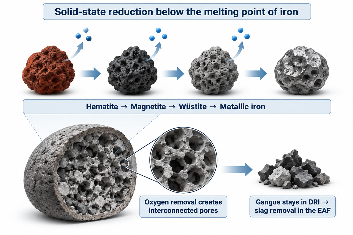
DRI is produced by the reduction of iron ore in the solid state at temperatures below the melting point of iron (1,538 °C). The production of iron in a direct reduction furnace uses solid-state reduction to produce iron without melting the ore. This involves a counter-current reducing-gas stream of hydrogen and carbon monoxide—or solid carbon derived from coal—to remove oxygen from hematite (Fe2O3) to magnetite (Fe3O4) and then to wüstite (FeO). The final reduction step converts wüstite into metal iron (Fe).
Since oxygen leaves the crystal lattice without melting, each reduced pellet or lump forms an interconnected honeycomb of microscopic pores. Direct-reduced iron possesses this kind of porous microstructure, and because of it, sponge iron is the traditional name of this material in the steel industry. This is also why cold DRI has an apparent density of 3.4–3.6 g/cm3 as compared to 7.8 g/cm3 of solid iron, as stated in the IIMA DRI specification.
Under U.S. federal greenhouse-gas reporting rules in 40 CFR Part 98 Subpart Q for Iron and Steel Production, a direct reduced iron furnace not collocated with an integrated iron and steel manufacturing process falls within the iron and steel production source category; unlike a traditional blast furnace, the direct reduction furnace retains gangue oxides in its solid product. For the broader process overview, including furnace routes, product forms and steelmaking integration, please read our 還元鉄プロセスガイド. This guide focuses on plant equipment selection, feedstock specs, and melting shop integration.
| パラメータ | Gas-Based Shaft DRI | Coal-Based Rotary Kiln DRI | Blast Furnace Pig Iron / Hot Metal |
|---|---|---|---|
| Physical state at discharge | Solid porous pellets or lump | Solid porous sponge iron + char | Liquid hot metal or solidified pigs |
| Operating temperature window | Solid state; temperature depends on shaft design | Solid state; temperature depends on rotary-kiln design | Molten iron; plant-specific tapping temperature |
| Primary reducing agent | Reformed natural gas (H2 + CO) or H2 | Non-coking coal (Boudouard CO) | Metallurgical coke from coking coal + PCI |
| Total iron content (Fetotal) | Supplier assay; verify total iron on the agreed basis | Supplier assay; verify total iron on the agreed basis | Supplier assay; verify total iron on the agreed basis |
| Metallization degree | Verify product metallization against the purchase specification | Verify product metallization against the purchase specification | ~100% (fully reduced liquid metal) |
| Combined carbon content | Carbon content adjustable as Fe3C; confirm the product assay | Process-dependent; verify total and combined carbon | 3.5–4.5 wt% C (IIMA general pig-iron specification) |
| Gangue removal stage | Retained in pellet; slagged in EAF | Retained in sponge; slagged in EAF/IF | Removed as liquid BF slag before BOF |
| Residual tramp elements (Cu, Ni, Sn) | Low residuals depend on virgin ore purity; verify each element | Verify residual elements separately; sulfur pickup also depends on coal | Low residuals depend on virgin ore purity; verify each element |
Gas-Based Shaft Furnaces vs. Coal-Based Rotary Kilns
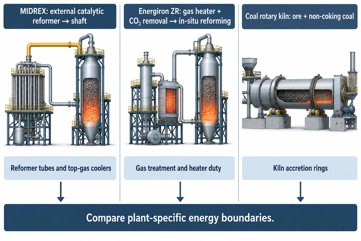
Production of Industrial DRI through different reactor types is driven by local energy economics. There are two dominant reactor types: gas-based vertical shaft furnaces and coal-based horizontal rotary kilns. According to the Midrex 2025 World Direct Reduction Statistics, world output reached 151.0 million tons in 2025, with MIDREX shaft-furnace plants generating 82.3 million tons, 81.5% of all shaft-furnace production globally, while rotary kilns accounted for the bulk of coal-based output in India and southern Africa.
How does a gas-based DRI shaft furnace differ from a coal-based rotary kiln?
A coal-based rotary kiln tumbles ore and non-coking coal horizontally; its product chemistry and throughput depend on the ore, coal and kiln design.
In a gas-based direct reduction plant, iron ore pellets and lump ore descend by gravity through a vertical refractory-lined shaft furnace while hot reducing gas (H 2 + CO derived from natural gas, syngas, or hydrogen) flows upward. The IIMA DRI production route comparison states that the two major commercial shaft technologies, in the reforming of hydrocarbons to reducing gas, differ in the following ways:
- External stoichiometric/CO2 reformer route (MIDREX): Recycled top gas containing CO2 and H2O is cleaned, compressed, mixed with fresh natural gas, and heated inside alloy catalyst tubes at the specified reformer temperature to generate a high-reductant gas stream without requiring an external steam boiler.
- Zero-reformer / in-situ reforming route (Energiron ZR): Recycled top gas undergoes wet scrubbing and CO2 removal, then mixes with natural gas, oxygen, and steam before entering the shaft at elevated pressure , where metallic iron inside the burden acts as the reforming catalyst under the selected operating conditions.
- Coal-based rotary kiln route (SL/RN, Jindal, Codir): Graded lump ore or pellets, non-coking coal, and dolomite desulfurizer rotate inside an inclined refractory cylinder ; volatiles and carbon monoxide generated via the Boudouard reaction (C + CO2 → 2CO) reduce iron oxides to metallic iron during the kiln residence time.
In a 2025 Journal of Cleaner Production technical analysis of flexible DRI systems, the gas-based shaft reactor is integrated with high-temperature electrolysis for hydrogen production, so specific energy consumption belongs to that integrated system boundary. Coal-based rotary kilns also have energy losses from kiln shell radiation, unburned char, and kiln off-gas. Some recoverable off-gas heat can be used in a waste-heat recovery boiler in the power island.
| Design / Operating Metric | MIDREX Shaft Furnace | Energiron ZR Shaft Furnace | Coal-Based Rotary Kiln |
|---|---|---|---|
| Single-module unit capacity | Specify design throughput and annual operating hours | 0.25–2.5 Mt/yr (Tenova technology range) | Specify design throughput and annual operating hours |
| Shaft / reactor pressure | Low shaft pressure; specify bar abs or barg explicitly | Elevated shaft pressure; specify bar abs or barg explicitly | Near atmospheric (slight draft) |
| Specific thermal energy | Plant-specific GJ/t DRI; define the energy boundary | Plant-specific GJ/t DRI; define the energy boundary | Plant-specific GJ/t DRI; define the energy boundary |
| Reducing gas preparation | External catalytic CO2/steam reformer | Process gas heater + CO2 removal unit | In-kiln coal devolatilization + char gasification |
| Typical product carbon | Adjust to the selected process and EAF carbon balance | Typically 1.5–4.5 wt% C (Tenova) | Adjust to the selected process and EAF carbon balance |
| Product sulfur pickup | Verify ore, fuel and product sulfur assays | Verify ore, fuel and product sulfur assays | Verify wt% S; sulfur-bearing coal may require dolomite |
| Example maintenance risks to assess for the selected flowsheet | Reformer alloy tube creep & top-gas cooler fouling | コ2 amine reboiler fouling & process heater duty | Fayalite (2FeO·SiO2) accretion ring build-up |
For a broader comparison of how the iron production route integrates with electric mini-mills versus blast-furnace integrated steelworks, see our analysis of mini-mill versus integrated steel mill architectures.
Feedstock Engineering: DR-Grade Pellets vs. BF-Grade Pellets
A direct reduction process uses pelletized iron ore or natural lump ore with a well-defined chemical composition and high mechanical strength. Because solid-state reduction doesn’t melt the burden or tap a separate ironmaking slag, most of the silica (SiO2), alumina (Al2O3), phosphorus and titanium entering the shaft furnace exits through the sponge iron and reports directly to the steelmaking furnace.
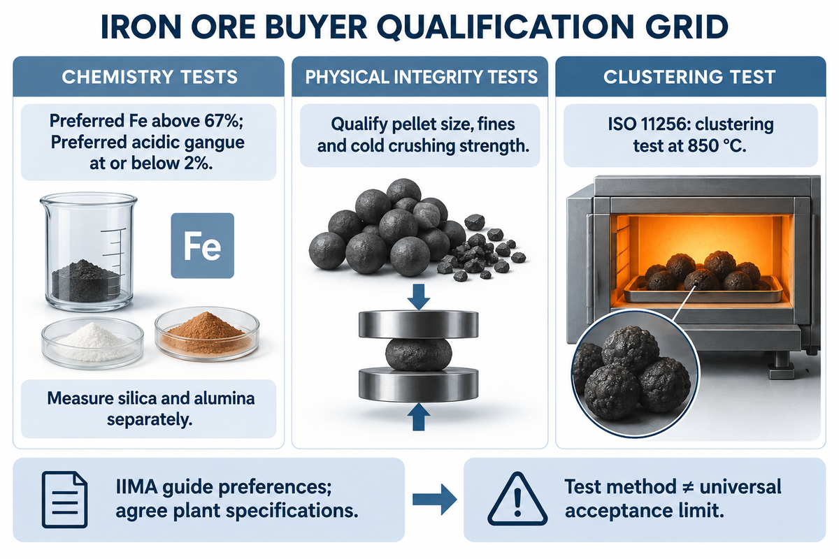
As reported in S&P Global’s analysis of DR-grade pellet supply constraints, direct-reduction quality depends on securing suitable high-iron, low-gangue feed; an IIMA-authored guide published by Midrex lists preferred Fe above 67% and combined SiO2 + Al2O3 at or below 2%, with actual specifications agreed for the plant. Obtaining cheaper blast-furnace (BF) pellets without adjusting downstream flux and power costs can increase the total cost of steelmaking in a DRI project.
Can blast furnace pellets be used in a DRI shaft furnace?
Standard blast furnace pellets can be used in some DRI shaft furnaces, but typically contain less total iron and more acidic gangue (SiO2 + Al2O3) than DR-grade pellets. In a blast furnace, that gangue melts into liquid slag before steelmaking; in a solid-state DRI shaft furnace, retained gangue increases the EAF slag volume, lime consumption and electrical power demand, with the actual penalty and clustering risk depending on ore chemistry and plant conditions.
Beyond gangue chemistry, shaft furnaces require pellets that resist solid-state sintering (sticking or clustering) under compressive load. Under ISO 11256:2015 (Determination of the clustering index for shaft direct-reduction feedstocks), an approximately 2,000 g test portion is isothermally reduced at 850 °C under a fixed reducing gas mixture (45% H2, 30% CO, 15% CO2, 10% N2) with a 147 ± 2 kPa static load applied after 60 minutes of reduction and then disaggregated in a tumbling drum. Coating selection and dosage should be validated for the ore and process so freshly reduced metallic iron surfaces resist sticking; ISO 11256 defines a test method rather than a universal commercial acceptance limit.
| 指定 パラメーター | DR-Grade Pellet Target to Qualify | BF-Grade Pellet Substitution Check | Consequence of Off-Spec Feed in DRI-EAF |
|---|---|---|---|
| Total iron (Fetotal) | Generally at least 67% Fe; confirm the contracted assay | Generally 65% Fe or less; assess iron-unit yield | Lower metallic yield per ton of charged DRI |
| Acidic gangue (SiO2 + Al2O3) | Acid gangue: maximum 3.5%; ideally maximum 2% | Measure silica and alumina separately | Extra lime flux and EAF power demand depend on gangue composition |
| Basic oxides (CaO + MgO) | CaO and MgO: include each oxide in the slag balance | Measure each oxide and include it in the slag balance | Self-fluxing basicity reduces EAF lime additions |
| Phosphorus (P) | Set the limit from steel grade and refining capability | Set the limit from steel grade and refining capability | Higher EAF oxidizing slag demand for dephosphorization |
| Sulfur (S) | Set the limit from process and steelmaking requirements | Set the limit from process and steelmaking requirements | H2S can poison reformer catalyst; assess sulfur release and gas treatment |
| Pellet size fraction (9–16 mm) | About 95% in the 9–16 mm band (Midrex) | Qualify the required pellet size band and permeability | Wide size spread increases shaft pressure drop (ΔP) |
| Undersize fines (<5.0 mm) | Agree a fines limit at the furnace screen | Measure degradation through the handling route | Gas channeling and dust carry-over into top-gas scrubber |
| Cold Crushing Strength (CCS) | Agree the minimum cold crushing strength per pellet | Test pellet cold crushing strength for the proposed blend | Bed crushing under the shaft burden generates fines |
| Clustering Index (ISO 11256 at 850 °C) | Agree a maximum after testing the selected coating | Test clustering under the proposed H2/CO conditions | Cluster arches block burden descent and force shutdown |
Inside the Shaft Furnace: Reduction Zones, Gas Reforming, and Carburization
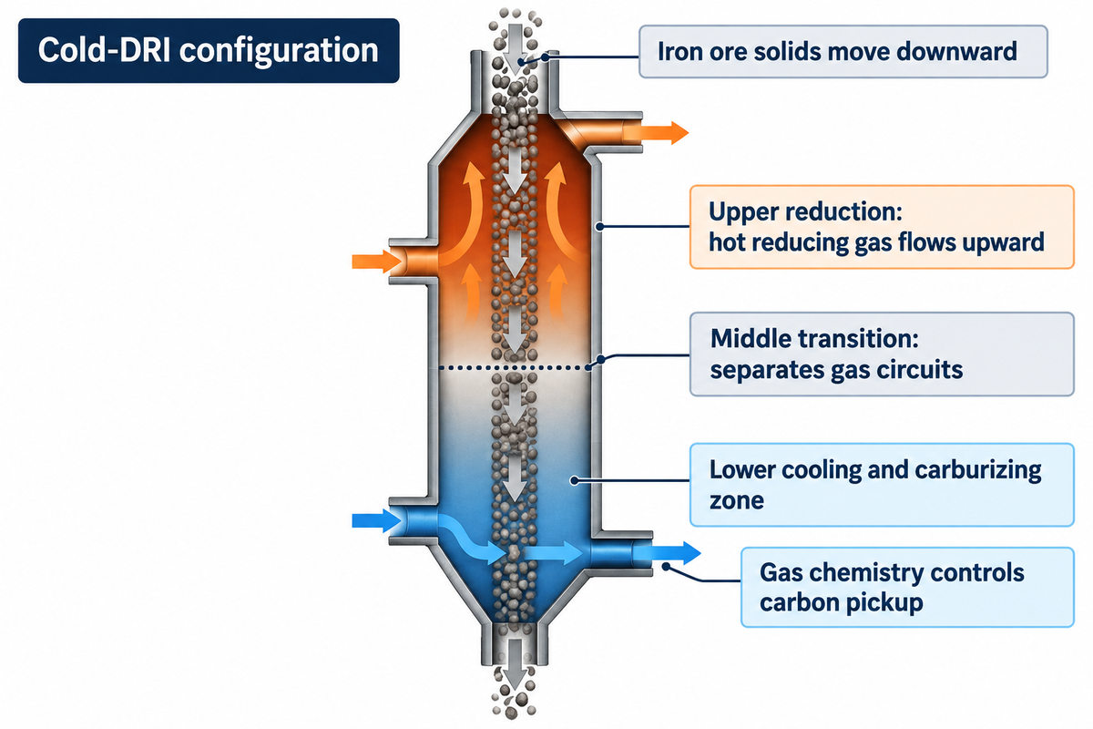
The cold-DRI shaft configuration described here operates as a three-zone counter-current chemical reactor where solid iron ore particles move downward while distinct gas circuits control reduction, transition, and cooling. As modeled in CPFD Barracuda gas-solid flow simulations of DRI shaft furnaces and disclosed in WIPO Patent Application WO2024170464A1, uniform radial gas distribution across the burden is critical to avoid cold channels through which low metallization product is discharged.
- Upper Reduction Zone : Hot reducing gas containing H2 and CO enters through circumferential bustle ports and flows upward through the bed of descending pellets.
- Middle Transition Zone: Located between the bustle gas ports and the lower cooling loop, this buffer zone isolates the upper reducing atmosphere from the lower cooling circuit and allows methane (CH4) and carbon monoxide to diffuse into freshly reduced iron pores.
- Lower Cooling and Carburizing Zone (configured for cold or hot product discharge): In cold-DRI plants, cooling gas rich in natural gas (CH4) circulates through the conical bottom. Methane cracks endothermically on catalytic metallic iron surfaces (3Fe + CH4 → Fe3C + 2H2), while CO disproportionates via the Boudouard reaction (2CO → C + CO2), altering the balance of cementite (Fe3C) and free carbon; this does not remove DRI handling and reoxidation hazards.
According to a 2024 Engineering journal review of direct reduced iron challenges, the ratio of H2 to CO in the bustle gas and the residence time in the transition/cooling zones, determine what fraction of product carbon is chemically combined as cementite (Fe3C, with a process-dependent share of total carbon) versus free, sooty carbon on the surface of pellets.
Metallization Degree and Carbon Content: How DRI Quality Controls EAF Performance
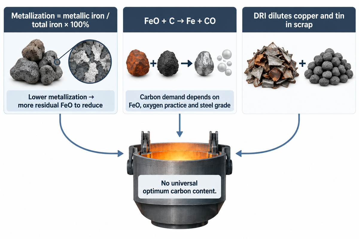
In electric arc furnaces, DRI quality is evaluated using two interrelated chemical parameters: the degree of metallization and total carbon content, including the share present as cementite. The degree of metallization characterizes the percentage of the total iron in sponge that’s converted to metallic iron.
Metallization (%) = (Femetallic ÷ Fetotal) × 100
Residual iron oxide in DRI is commonly represented as wüstite (FeO) in a simplified melt-shop balance. As detailed in IspatGuru’s metallurgical analysis of DRI in the electric arc furnace そして Missouri S&T’s experimental study on the melting behavior of direct reduced iron in molten steel, unreduced FeO must be reduced endothermically in the EAF bath by dissolved carbon (FeO + C → Fe + CO). A lower metallization degree increases the residual oxide burden; the electrical energy penalty depends on DRI charge share, carbon availability, iron recovery and furnace operation.
Why is direct reduced iron blended with scrap in an electric arc furnace?
Direct reduced iron is blended with scrap in an electric arc furnace to dilute residual elements such as copper and tin that are difficult to remove during conventional steelmaking. The required DRI share follows from the scrap assay and target steel chemistry, enabling low-residual flat-rolled, automotive and deep-drawing steel grades.
What is the ideal carbon content in direct reduced iron for EAF steelmaking?
For electric arc furnaces charging DRI alongside scrap, the ideal combined carbon content (present primarily as cementite, Fe 3 C) depends on residual FeO, oxygen practice and the desired steel grade. Carbon reduces residual FeO and can react with injected oxygen to produce carbon monoxide bubbles for foamy slag arc shielding, while the useful chemical heat and any decarburization penalty depend on furnace operation.
The interaction of metallization, carbon and charge mix is examined in MDPI Energies’ study on scrap and DRI ratios in EAF energy balances, but it does not establish a universal rule that pushing metallization above a fixed value worsens melt-shop efficiency. Without sufficient available carbon to react with FeO inside the melting pellet, CO evolution and foamy slag can weaken; weaker arc shielding can increase radiation toward water-cooled panels and refractory walls, while heat losses and the need to inject powdered carbon depend on actual bath conditions and recovery of internal cementite or injected carbon.
Worked Example: DRI-to-EAF Charge Balance and Slag Calculation
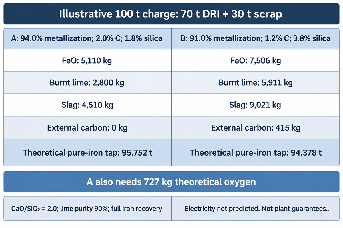
To assess the same parameters for two competing pellet or DRI supply offers, process engineers and raw material buyers at a steel plant can apply the following DRI-to-EAF Charge Balance Worksheet. The calculation compares two hypothetical 100-tonne metallic charges (70 t cold DRI + 30 t shredded steel scrap), with liquid steel output determined by iron recovery rather than assumed equal to the input charge, at a target slag basicity (B2 = CaO / SiO2 ) of 2.0.
Explicit boundary and assumptions for the DRI-to-EAF Charge Balance Worksheet
All inputs below are transparent engineering calculation assumptions, not private plant records or guaranteed vendor performance. Both cases charge 70.0 t of cold DRI (at 40 °C) and 30.0 t of low-residual shredded scrap on a 100 t charge basis, with DRI assumed to contain only iron, residual FeO, carbon and silica. Scrap consists of 29,550 kg of iron and 450 kg of inert oxides in each case; those oxides contribute no CaO or SiO2. Burnt lime contains 90% effective CaO and 10% inert material, all of which enters the slag. This idealized calculation assumes complete iron recovery, complete FeO reduction, no dust or iron loss, no carbon remaining in the tap, and perfect utilization of carbon to form CO; it does not predict electrical power consumption or provide an operating recipe.
For this assumed composition, the total-iron mass fraction is (1 − carbon fraction − silica fraction) / [1 + (1 − metallization) × 15.999 / 55.845], with metallization expressed as a fraction; residual FeO mass follows from the unreduced iron fraction. The resulting theoretical pure-iron taps are 95.752 t in Case A and 94.378 t in Case B, and the slag figures include the lime impurities and scrap oxides; Case A additionally requires 727 kg of theoretical oxygen to convert surplus carbon to CO, while Case B requires no supplementary oxygen within this simplified balance. Neither these ideal yields nor the theoretical carbon additions are plant performance guarantees; actual iron losses, carbon efficiency, tap chemistry and residual FeO must be measured before comparing supply offers.
| Charge / Melt-Shop Parameter | 単位 | Case A: Assumed DR-Grade DRI | Case B: Assumed High-Gangue DRI | Delta (Case B vs. Case A) |
|---|---|---|---|---|
| Charged cold DRI mass | t / heat | 70.0 | 70.0 | 0.0 t |
| DRI metallization degree | % | 94.0% | 91.0% | −3.0 percentage points metallization |
| DRI carbon content | wt% | 2.0% | 1.2% | −0.8 percentage points C (−560 kg C/heat) |
| DRI acidic gangue (assumed entirely SiO2) | wt% | 1.8% | 3.8% | +2.0 percentage points acidic gangue |
| Acidic gangue mass entering EAF from DRI | kg / heat | 1,260 | 2,660 | +1,400 kg gangue |
| Unreduced FeO entering EAF from DRI | kg / heat | 5,110 | 7,506 | +2,396 kg FeO to reduce |
| Required CaO flux at B2 = 2.0 | kg / heat | 2,520 | 5,320 | +2,800 kg CaO |
| Burnt lime addition (at 90% CaO purity) | kg / heat | 2,800 | 5,911 | +3,111 kg burnt lime |
| DRI-derived EAF slag mass (incl. silica + lime + scrap oxides) | kg / heat | 4,510 | 9,021 | +4,511 kg extra slag per heat |
| Theoretical external carbon required for FeO reduction | kg / heat | 0 | 415 | +415 kg theoretical carbon |
| Net EAF electrical energy consumption | kWh / t liquid steel | Not predicted | Not predicted | Not predicted |
Consider the inputs that affect operating costs in Case B: even if the high-gangue DRI is offered at a discount per metric ton, melting an extra 4,511 kg of slag and reducing an extra 2,396 kg of FeO per 100 t charge calls for 3,111 kg of additional burnt lime and 415 kg of extra injection carbon under these idealized assumptions, while electrical energy consumption and tap-to-tap time require a separate furnace heat balance.
Hot DRI, Cold DRI, and Hot Briquetted Iron (HBI): Handling, Passivation, and Shipping
Safe production and handling of sponge iron after it leaves the shaft furnace determines both its EAF thermal credit and its maritime transport classification. When a direct reduction plant is situated next to the melt shop, uncooled DRI can be discharged at temperatures of 600 to 700 °C and transported to the electric furnaces used for steel production via MIDREX HOTLINK or nitrogen pneumatic transport, enhancing the overall efficiency of the process.
Charging hot DRI carries sensible heat into the EAF, reducing the energy needed to melt the charge; in Midrex’s reported hot-transport-vessel example, heats receiving one 90-tonne hot DRI vessel saved an average 60 kWh/t of liquid steel; the article equates this to 120 kWh/t at a 100% hot DRI charge, with results specific to that operating example. When the iron must be stored outdoors or shipped by sea as merchant metallics, however, porous sponge iron presents a severe exothermic reoxidation hazard. As explained in the IIMA Hot Briquetted Iron (HBI) technical guide そして SME’s review of DRI passivation techniques, compacting hot DRI between the rolls of a briquetting press at temperatures above 650 °C produces pillow-shaped hot-briquetted iron briquettes with an apparent density >5.0 g/cm3, reducing internal pore volume and reactivity with moisture.
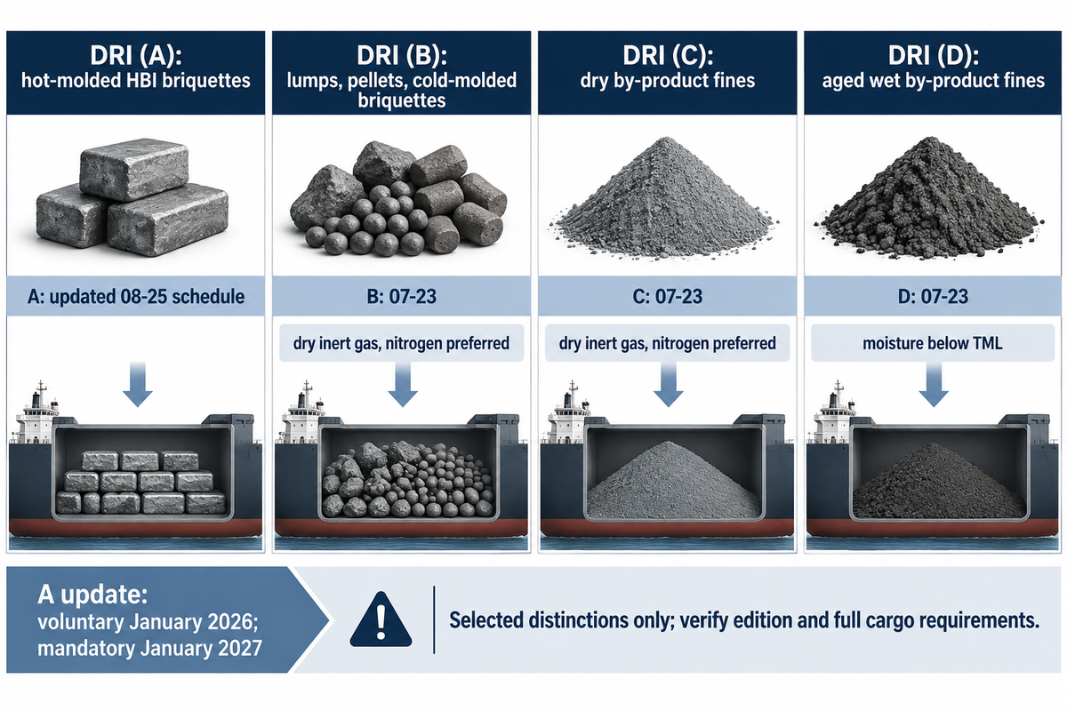
In accordance with the International Maritime Organization’s IMSBC Code – including Amendment 07-23 that entered into force on January 1, 2025, and is outlined in the International Group of P&I Clubs DRI carriage circular – maritime shipments are grouped into four separate schedules:
The table summarizes selected distinctions, not a complete cargo acceptance or ventilation procedure; the DRI (A) row shows the revised Amendment 08-25 requirements, while the other rows summarize 07-23. The updated DRI (A) schedule allows voluntary adoption from January 2026 and enters into force in January 2027, so shippers must confirm the applicable edition and full cargo-specific requirements before booking a voyage.
| IMSBC Schedule | Form of DRI Covered | Density / Particle Size | Moisture & Hold Atmosphere Rules |
|---|---|---|---|
| DRI (A) | Hot-molded briquettes (HBI); 08-25: total Fe ≥88% | Apparent density >5.0 g/cm3; fines (<6.35 mm) ≤5% | 08-25: moisture ≤1.0%, temperature ≤65 °C; surface ventilation + H2 monitoring |
| DRI (B) | Lumps, pellets, and cold-molded briquettes | Lumps/pellets: average 6.35–25 mm; fines <6.35 mm ≤5% | Pre-loading moisture certificate <0.3%; cargo temperature ≤65 °C; dry inert gas (nitrogen preferred) (O2 <5%) |
| DRI (C) | Dry by-product fines and screenings | Average particle size <6.35 mm; no particles >12 mm | Moisture ≤0.3%; cargo temperature ≤65 °C; dry inert gas (nitrogen preferred) as per DRI (B) |
| DRI (D) | Aged wet by-product fines (new 2025 schedule) | Average particle size <6.35 mm; aged outdoors ≥30 days | Moisture ≥2.0% and <TML; pre-loading temperature ≤65 °C and H2 evolution check |
Process Gas Loop Bottlenecks: Reformer, Cooler, and Heat Exchanger Maintenance
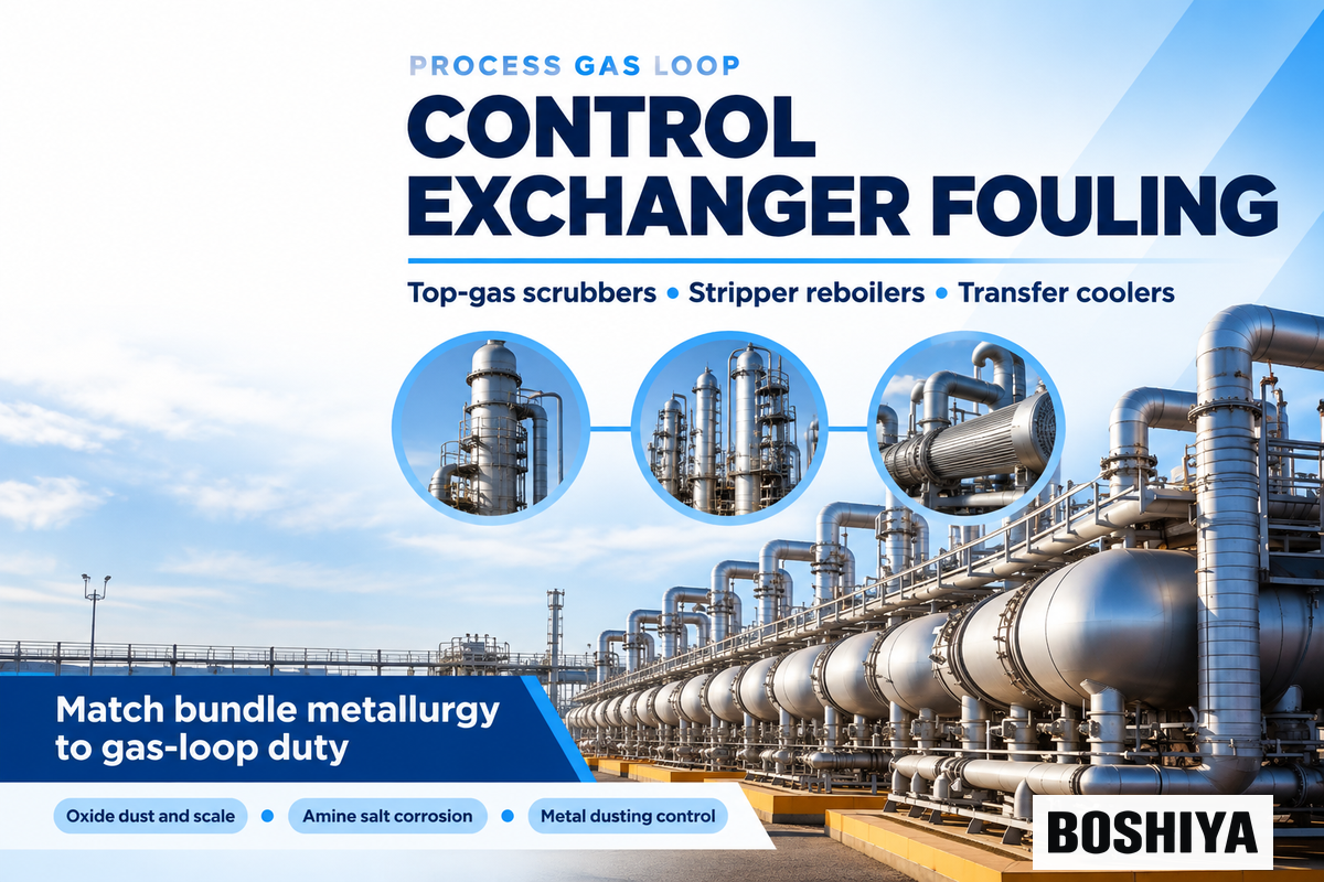
While metallurgical evaluations are focused on the reduction shaft, day-to-day plant availability in a gas-based DRI unit also depends on the closed-loop gas conditioning and heat-recovery train. A process-dependent share of the spent top gas leaving the shaft furnace is scrubbed, cooled, compressed, treated for CO2 removal where the flowsheet requires it, and reheated before returning to the bustle ports.
As documented in Heat Exchanger World’s engineering analysis of industrial fouling, Heat Exchanger World’s review of thermal resistance and pressure drop penalties, 、 および Chemical Engineering’s guide to waste-heat recovery exchangers, gas-loop exchangers can experience fouling, corrosion and thermal damage, depending on the service. In addition, MetalTek’s metallurgical guide for DRI reformer tubes highlights that reformer components require resistance to creep, thermal fatigue, oxidation and carburization for the specified operating conditions. Practitioners on Eng-Tips heat exchanger recirculation threads similarly emphasize sizing recirculation exchangers with adequate fouling allowance and cleanout access.
の The gas-loop maintenance map below classifies the exchangers in the process gas loop by potential deposit chemistry and inspection needs; it is a screening aid across alternative flowsheets: a plant does not necessarily contain all nine services, so set alarm limits and cleaning procedures from equipment design, solvent chemistry and the clean-operation baseline. For more information on shell-and-tube mechanical design, please refer to our 熱交換器 汚れ ガイド そして tube-sheet heat exchanger engineering guide.
| Gas Loop Zone & Equipment | Process Stream & Temperature Window | Potential Fouling / Degradation Mode | Inspection Trigger & Maintenance Review |
|---|---|---|---|
| 1. Top-Gas Wet Scrubber Quench Cooler | Spent top gas + recirculated water | Entrained oxide dust; water-side scale where chemistry permits | ΔP rise or outlet gas temperature rise; investigate fouling before cleaning the tube bundle |
| 2. Process Gas Compressor Aftercooler | Compressed recycle gas | Oxide sludge; biological deposits or mineral scale on the water side | Compressor discharge temp creep; removable bundle hydroblasting |
| 3. Cooling-Zone Gas Scrubber Cooler | Lower-shaft cooling gas | Carbon deposits or iron-bearing dust, depending on cooling-gas chemistry | Cold DRI discharge temperature above the design limit; investigate before high-pressure lance cleaning |
| 4. CO2 Absorber Lean/Rich Exchanger | MDEA / activated amine or potassium carbonate | Solvent degradation deposits, corrosion products or particulate blockage | Approach temperature widening; identify deposits before chemical circulation or mechanical flushing |
| 5. CO2 Stripper Reboiler Bundle | Rich solvent + low-pressure steam / process gas | Solvent degradation or localized corrosion; inspect chemistry and hot surfaces | Rising CO2 slip in sweet gas; inspect solvent and reboiler duty before bundle pull |
| 6. Overhead CO2 Reflux Condenser | Wet CO2 stripper overhead vapor | Wet CO2 corrosion; select materials from condensate chemistry and design conditions | Condensate iron count spike; tube plugging or retubing |
| 7. Feed Gas Preheater (Convection Bank) | Mixed process gas + flue gas | Flue-side deposits or process-side carbon deposition; distinguish the affected side | Flue draft loss + preheat shortfall; external sootblowing / cleaning |
| 8. Reformer / Heater Transfer Line Cooler | Reformed H2/CO gas; assess temperature and gas chemistry | Carburization or metal dusting under susceptible temperature and gas-composition conditions | Review gas chemistry, metal temperature and alloy suitability |
| 9. Reformer Radiant Catalyst Tubes | CH4 + CO2 + H2O over Ni catalyst | Tube creep and carburization; nickel catalyst sulfur poisoning assessed separately | Optical pyrometer tube-wall checks + diameter creep strain audit |
RFQ & Turnaround Checklist for DRI Process Gas Coolers and Heat Exchanger Bundles
- Process gas composition & dew point: Specify H2, CO, CO2, H2O, CH4, and trace H2S (ppmv) across normal and startup conditions.
- Particulate loading: State expected iron oxide and carbon dust carry-over (mg/Nm3) and the proposed tube-side velocity range, balancing settling, erosion and pressure drop.
- Metallurgy & corrosion allowance: Assess carbon steel, 316L / duplex 2205 and high-Cr/Ni alloys for the actual wet CO2 chemistry, metal temperature and corrosion exposure; confirm material suitability through a project-specific corrosion assessment.
- Bundle extraction envelope: Specify TEMA type (e.g., AEL, BEM, or pull-through floating head) and turnaround heat exchanger bundle cleaning clearance for hydroblasting lances.
Hydrogen-Based DRI (H2-DRI) and Smelting Reduction: What Changes for Plant Equipment?
Replacing natural gas or coal with green or low-carbon hydrogen in the hydrogen-based direct reduction of iron fundamentally changes the thermodynamic balance and metallurgy of the shaft, as compared to a conventional blast furnace. In a natural gas furnace, endothermic H2 reduction (Fe2O3 + 3H2 → 2Fe + 3H2O) is partially offset by exothermic CO reduction (Fe2O3 + 3CO → 2Fe + 3CO2) and cementite formation.
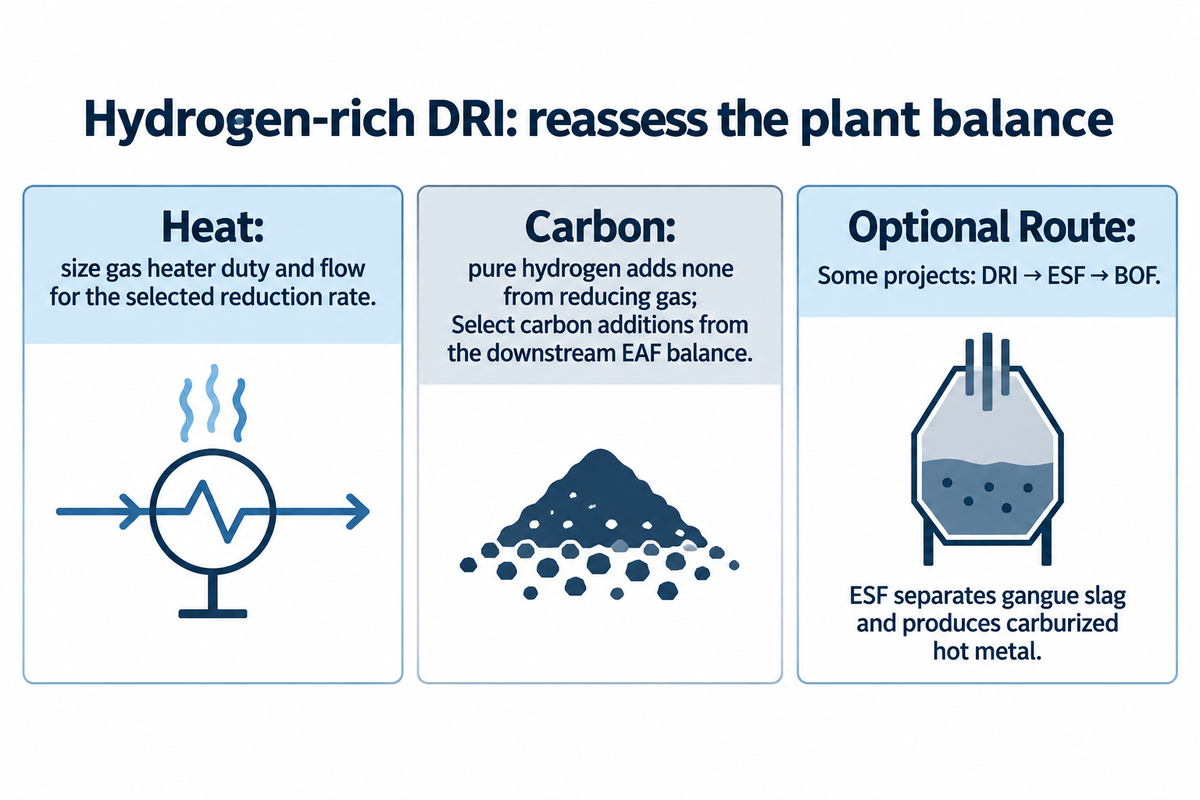
When a hydrogen-based direct reduction plant transitions toward a hydrogen-rich reducing gas stream, three engineering changes occur simultaneously:
- Revised process-gas heat balance: Because pure hydrogen reduction of iron oxides to metallic iron is endothermic overall, the reducing gas heater or electric gas heater requires thermal duty and gas flow rates sized for the selected gas utilization to maintain the specified bed temperature and reduction rate.
- Carbon pickup depends on the gas supply: pure H2 contributes no carbon to sponge iron in the reduction zone. As discussed in Midrex’s hydrogen DRI and EAF analysis, hydrocarbon cooling gas or controlled bio-methane/natural-gas trim injection in the lower zone can change product carbon, with carbon additions selected from the downstream EAF balance for foamy slag operation rather than a universal requirement to discharge hot or inject methane.
- Two-step DRI + Electric Smelting Furnace (ESF) pathway for BF-grade pellets: Because global DR-grade pellet supply is constrained, some projects are developing an intermediate submerged-arc electric smelting furnace (ESF / melter) between the H2-DRI shaft and a basic oxygen converter (DRI-ESF-BOF). The ESF melts high-gangue BF-grade H2-DRI, separates gangue into liquid slag, and taps carburized hot metal into existing BOF shops.
Direct Reduced Iron (DRI) Frequently Asked Questions
直接還元鉄 (DRI) と熱練炭鉄 (HBI) の違いは何ですか?
Direct reduced iron (DRI) is porous sponge iron in pellet or lump form with an apparent density of 3.4–3.6 g/cm3 and high internal surface area. Hot briquetted iron (HBI), classified as DRI (A) under the IMO IMSBC Code for maritime bulk shipping, is DRI compacted at temperatures above 650 °C into dense pillow-shaped briquettes with an apparent density greater than 5.0 g/cm3, reducing porosity and susceptibility to moisture absorption, self-heating, and reoxidation.
直接還元鉄がスポンジ鉄と呼ばれるのはなぜですか?
As oxygen leaves in the form of H2O and CO2 gas, each particle retains its external shape while developing a microscopic network of interconnected voids that resembles a porous sponge under a microscope. The name describes this porous structure; it does not identify a separate production route or a guaranteed chemical specification.
熱い DRI 充電は電気アーク炉でどれくらいの電気エネルギーを節約しますか?
シャフト炉から電気アーク炉にホット DRI を直接充電すると、コールド DRI を充電する場合と比較して電気使用量が削減されますが、節約効果は新しい鋼を製造する際の充電シェア、温度、動作に依存します。 Midrex は、熱量 100% のホット DRI 充電で 120 kWh/t と比較して、100 トンあたり 1 トンのホット DRI 容器で節約された溶鋼の平均 60 kWh を報告しています。
直接還元鉄は純粋な水素で生成すると炭素を含みますか?
DRI reduced solely with pure hydrogen receives no carbon from the reducing gas; natural gas, biomethane, or CO can be injected into the transition or cooling zone to form cementite (Fe3C) before EAF melting.
What is the clustering index test for direct reduction iron ore pellets?
ISO 11256 measures pellet sticking by isothermally reducing an approximately 2,000 g sample at 850 °C with a 147 ± 2 kPa static load applied after 60 minutes of reduction in H2/CO/CO2/N2 gas and tumbling the clustered mass.
Specify Custom Process Gas Coolers and Heat Exchangers for Your DRI or Steel Plant
BOSHIYA fabricates custom ASME and TEMA shell-and-tube heat exchangers, top-gas quench coolers, CO2 stripper reboilers, and pressure vessels engineered for fouling-intensive metallurgical and chemical gas loops. Explore our steel and metal plant equipment portfolio または contact our engineering team with your process datasheet for a project-specific thermal and mechanical review.
参考文献と情報源
- 40 CFR Part 98 Subpart Q, Iron and Steel Production U.S. Environmental Protection Agency (eCFR).
- 40 CFR 98.173, Calculating GHG emissions for direct reduced iron furnaces and EAFs U.S. Environmental Protection Agency (eCFR).
- COREX reduction-shaft and melter-gasifier production and maintenance record (distinct from conventional DRI-only routes) U.S. Department of Energy OSTI.
- The Melting Behavior of Hydrogen Direct Reduced Iron in Molten Steel Missouri University of Science and Technology, Peacemaker Steelmaking Research Center.
- Direct Reduced Iron (DRI): Technical Specification and Properties International Iron Metallics Association (IIMA).
- Hot Briquetted Iron (HBI): Compaction Density and Shipping Guide International Iron Metallics Association (IIMA).
- DRI Production Routes: Shaft Furnaces vs. Rotary Kilns International Iron Metallics Association (IIMA).
- 2025 World Direct Reduction Statistics: Global DRI Production Reaches 151.0 Mt Midrex Technologies, Inc.; 2025 production data, published September 2026.
- ISO 11256:2015, Iron ore pellets for shaft direct-reduction feedstocks, Determination of the clustering index International Organization for Standardization.
- Carriage of Direct Reduced Iron (DRI) under IMSBC Code Amendment 07-23 International Group of P&I Clubs, 2025.
- Impact of Scrap and Hydrogen-Based Direct Reduced Iron Ratios on Energy Demand, Emissions, and Oxygen Management in Green Steelmaking MDPI Energies, 2026.
- Technical analysis of high-efficiency and flexible direct reduced iron systems Journal of Cleaner Production, 2025.
- Development of Direct Reduced Iron: Challenges and Pathways Engineering, Chinese Academy of Engineering, 2024.
- Use of Direct Reduced Iron in Electric Arc Furnace Steelmaking IspatGuru Metallurgical Reference.
- Heat Exchanger Fouling in Practice: Understand & Mitigate 熱交換器 ワールド.
- Waste Heat Recovery Methods and Technologies in Process Gas Loops Chemical Engineering.
- WO2024170464A1, Method of producing direct reduced iron in a shaft furnace Google Patents, 2024.
- JP2025539600A, Process for producing direct reduced iron with cooling gas control Google Patents, 2025.